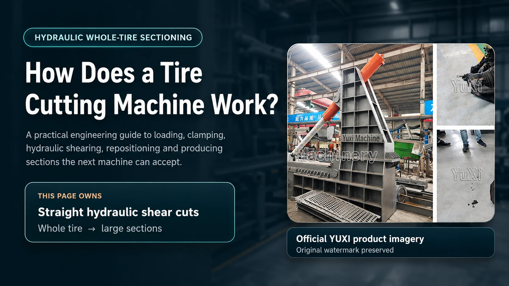
يُعد اختراق الشفرة للإطار اللحظة الأكثر وضوحًا. لكن هذه ليست العملية بأكملها. فالشرح المفيد يجب أن يشمل أيضًا كيفية دعم الإطارات الثقيلة وتثبيتها وإعادة وضعها وتحويلها إلى أجزاء يمكن للآلة التالية معالجتها.
تستخدم آلة قطع الإطارات الهيدروليكية آليات الدعم والتثبيت والقص المستقيم التي يتم التحكم فيها لتحويل الإطارات الكبيرة إلى أجزاء يسهل التعامل معها.
قد يقلل المشتري الذي يشاهد مقطع فيديو قصيرًا عن الآلة من شأن ما يحدث بسهولة. فالقاطع يتحرك مرة واحدة، ويفتح المطاط، ويبدو أن المهمة قد انتهت. لكن في الواقع، تلك الحركة المرئية ليست سوى مرحلة توصيل القوة. تبدأ دورة التشغيل عند تقييم الإطار وتحميله؛ وتنتهي عند إزالة الأجزاء المقبولة ونقلها إلى نقطة التجميع أو المعالجة التالية.
إجابة سريعة
تعمل آلة قطع الإطارات الهيدروليكية عن طريق وضع إطار كبير كامل أو معالج مسبقًا على منصة عمل مدعمة، وتحديد موضع القطع المطلوب، وتثبيت جسم الإطار، واستخدام أسطوانة هيدروليكية لدفع قاطع ثقيل عبر المطاط والحديد التسليحي. ثم تنسحب أداة القطع. ويقوم المشغل أو نظام المناولة المركب بإعادة وضع الجزء المتبقي من هيكل الإطار، وتثبيته مرة أخرى، وتكرار الحركة حتى يتم إنتاج العدد المطلوب من الأجزاء الكبيرة.
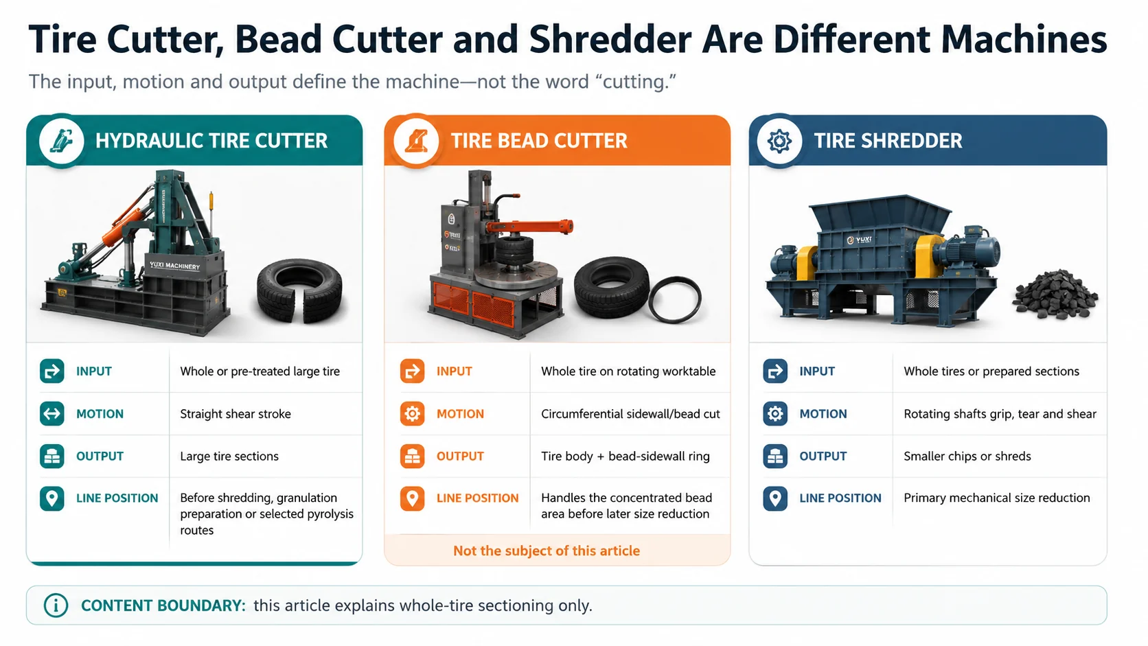
إن آلة قطع الإطارات YUXI يُستخدم هذا الجهاز كوحدة معالجة أولية في مشاريع الإطارات الخاصة بالشاحنات، والإطارات الراديالية المصنوعة بالكامل من الفولاذ، والإطارات الزراعية، والإطارات المخصصة للطرق الوعرة (OTR)، حيث تكون الإطارات الكاملة كبيرة الحجم أو صلبة أو غير منتظمة الشكل بحيث يتعذر تغذيتها مباشرةً بشكل مستقر. ويقوم الجهاز بتقطيع الإطارات إلى أجزاء لتتم عملية التقطيع لاحقًا، أو لتقليل حجم المطاط، أو لتجهيزها للتغذية في عمليات الانحلال الحراري المحددة، أو لتخزينها. ولا يتبع الجهاز محيط حافة الإطار، كما أنه لا ينتج رقائق نهائية.
يتم سحب السلك من مادة الحافة المُعدة مسبقًا باستخدام خطاف وعملية سحب هيدروليكية.
حزمة سلكية مركزة ذات حبيبات وحلقة مُعدة غنية بالمطاط.
مجموعة منفصلة لاستخراج الأسلاك.
آلة تقطيع الإطارات
تقوم الأعمدة الدوارة بالقبض والتمزيق والقص بشكل مستمر.
قطع أو شرائح أصغر حجمًا.
محتوى منفصل عن مبدأ عمل آلة التقطيع.
ابدأ بالمدخلات، والإجراءات، والمخرجات
يصبح فهم مبدأ العمل أسهل بكثير عندما تكون الحالات الثلاث ثابتة.
الإدخال
إطار شاحنة كامل أو معالج مسبقًا، أو إطار شعاعي مصنوع بالكامل من الفولاذ، أو إطار زراعي، أو إطار OTR، ضمن النطاق المعتمد للآلة الموردة. قد يكون الإطار سليمًا، أو مفتوحًا جزئيًا، أو قد تم فصل حافته مسبقًا، وذلك وفقًا لمسار المشروع.
الإجراء
يتم تثبيت الإطار وتقييده. ويقوم أسطوانة هيدروليكية بتحريك القاطع عبر المقطع العرضي المحدد. ثم يتراجع القاطع، ويتم إعادة وضع الجزء المتبقي من الإطار لإجراء عملية قطع أخرى.
الإخراج
قطع الإطارات الكبيرة. وهي أصغر حجمًا وأسهل في التعامل معها مقارنة بالإطار الأصلي، لكنها ليست رقائق مطاطية نهائية، ولا حبيبات، ولا مسحوق.
هذا الحد مهم من الناحية التجارية. فالمشتري الذي يطلب “مخرجات بحجم 50 ملم” عادةً ما يكون يقصد آلة التقطيع أو متطلبات التخفيض الثانوي للحجم، وليس المخرجات المباشرة لآلة تقطيع الإطارات الثقيلة. وعلى العكس من ذلك، فإن الإطار المستخدم في التعدين الذي لا يمكن تقديمه بأمان إلى آلة التقطيع قد يحتاج إلى عدة ضربات تقطيع قبل أن تصبح آلة التقطيع هي الآلة التالية المناسبة.
في الواقع: إن المواصفات الأكثر فائدة للمنتج النهائي ليست صورة جذابة لأربع قطع متساوية، بل هي الحد الأقصى لمحيط المقطع وشكله الذي يمكن أن تستوعبه بشكل ثابت القادوس أو الناقل أو آلة التقطيع أو فتحة التحميل الفعلية الموجودة في المرحلة التالية من العملية.
كيف تتحول الطاقة الهيدروليكية إلى حركة قص
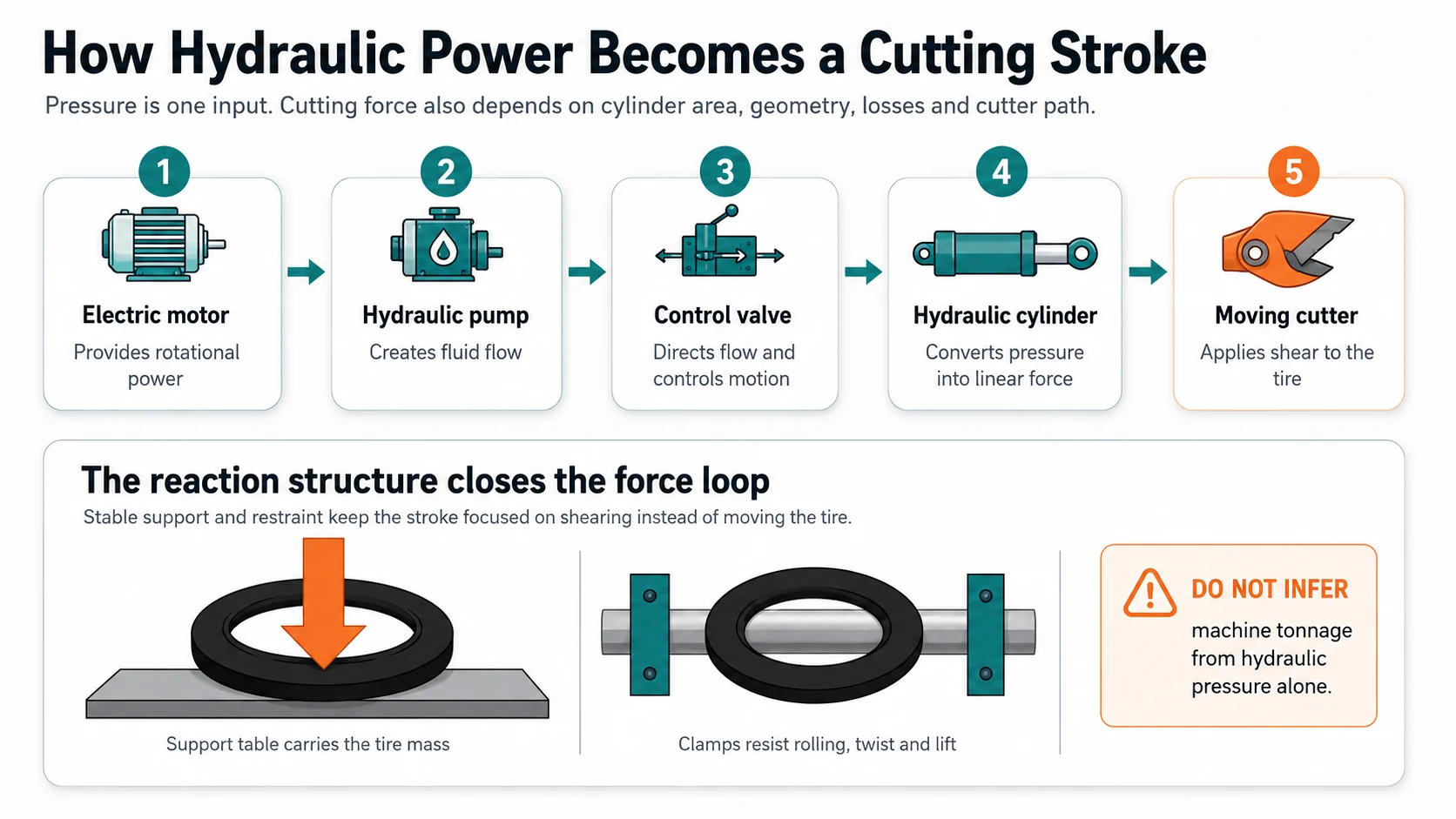
تصف شركة YUXI هذه الآلة بأنها تعمل بالطاقة الهيدروليكية. وهذا يوضح لنا مسار الطاقة بشكل عام، لكنه لا يبرر اختراع قيمة عامة للطاقة أو الضغط. تعتمد القدرة النهائية على القطع على التكوين الهيدروليكي والهيكلي المزودين.
تقوم الدائرة الهيدروليكية بتوليد الحركة الخطية والتحكم فيها؛ بينما يعمل الطاولة والمشبك والإطار على إكمال حلقة القوة.
1
يقوم المحرك بتشغيل المضخة الهيدروليكية
يوفر المحرك الطاقة الدورانية. وتولد المضخة التدفق الهيدروليكي. ويتيح التدفق تحرك الأسطوانة؛ ويرتفع ضغط النظام استجابةً للمقاومة. هذه المصطلحات مترابطة، لكنها ليست مترادفة.
2
تقوم الصمامات بتوجيه حركة السوائل والتحكم فيها
يقوم نظام التحكم بتوجيه التدفق بحيث تتقدم أداة القطع وتتوقف وتتراجع وفقًا للتسلسل المقصود. ويختلف الترتيب الدقيق للصمامات وطريقة التحكم في السرعة ومنطق الترابط باختلاف التكوين، لذا يجب التأكد من ذلك في الوثائق المرفقة.
3
يقوم الأسطوانة بتحويل الضغط إلى قوة خطية
بالنسبة للأسطوانة البسيطة، ترتبط القوة النظرية بالضغط الهيدروليكي ومساحة المكبس الفعالة. وتكون القوة الفعلية المتاحة أقل بعد احتساب الفاقد، كما يمكن أن تتأثر بهندسة نظام الوصلات أو ترتيب القواطع.
القوة النظرية للأسطوانة = الضغط الهيدروليكي × المساحة الفعالة للمكبس
نظرًا لأن صفحة المنتج المتاحة للجمهور لا تنشر قيمة موحدة للضغط أو قطر التجويف أو النسبة الميكانيكية، فإن هذه المقالة لا تحدد قيمة ثابتة لقوة القطع لكل تكوين من تكوينات YUXI.
4
تقوم القاطعة بتركيز تلك القوة على طول حافة القطع
يضغط القاطع على الإطار. يتشوه المطاط قبل أن ينفصل؛ أما الحبال الفولاذية وأجزاء أسلاك الحافة فتقاوم الضغطة بطرق مختلفة. ويقلل القاطع الحاد والمثبت بشكل صحيح من التشوه غير الضروري، لكن الآلة لا تزال بحاجة إلى صلابة هيكلية كافية للحفاظ على التحكم في مسار القطع.
5
يتحمل المشبك والطاولة والإطار الحمل
لا تختفي قوة القص عند الإطار. بل تعود عبر المادة المدعومة، والمنصة، والمشبك، والموجهات، والإطار. فإذا كان الإطار قادرًا على الدوران أو الارتفاع أو الالتواء، فإن جزءًا من الشوط يُستهلك في تحريك المادة بدلاً من قصها. ولهذا السبب، فإن عبارة “نظام هيدروليكي قوي” دون وجود دعامة مستقرة تُعد وصفًا غير مكتمل للتصميم.
الأجزاء الرئيسية ووظائفها الفعلية
المكون
الدور في العملية
نقطة التحقق من هوية المشتري
منصة العمل / طاولة الدعم
يحمل وزن الإطار ويوفر نقطة مرجعية ثابتة لعملية القطع.
تنظيم تسلسل الحركات وتقليل تعرض العامل لمنطقة التشغيل.
مفهوم الحماية، وموقع التحكم، وسلوك إعادة الضبط، والإيقاف في حالات الطوارئ، ومتطلبات التدريب الخاصة بالآلة.
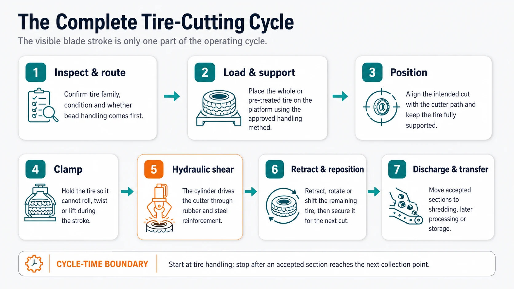
دورة القطع الكاملة المكونة من سبع خطوات
تتضمن الدورة الفعالة عمليات المناولة والتوجيه والتفريغ — وليس فقط الوقت الذي تتحرك فيه القاطعة.
1
افحص الإطار واختر مسار العملية
يقوم المشغل بتحديد فئة الإطار، والتحقق من وجود أي تشوهات ظاهرة أو مواد غريبة، والتأكد مما إذا كان المسار المعتمد هو القطع المباشر أم معالجة الحافة أولاً. وتشير شركة «يوشي» إلى أن بعض المشاريع تقوم بإزالة مادة الحافة قبل القطع، في حين تقوم مشاريع أخرى بقطع الإطارات الكبيرة أولاً؛ ويعتمد القرار على بنية الإطار والعملية اللاحقة.
2
تحميل الإطار وتوفير الدعم الكامل له
الإطار الكبير ليس قطعة خفيفة الوزن في ورشة العمل. فكتلته وقطره وميله إلى التدحرج هي العوامل التي تحدد ما إذا كان من الضروري التعامل معه يدويًّا أم باستخدام رافعة شوكية أو لودر أو رافعة أو أي أداة مساعدة أخرى. ويجب أن يصل الإطار إلى محطة القطع في وضع محدد بدقة وأن يظل مدعومًا طوال عملية وضعه في مكانه.
3
محاذاة الشق الأول
يتم وضع المقطع المقصود تحت مسار القاطع. ويُعد تحديد الموقع الصحيح قرارًا متعلقًا بالعملية: فهو يؤثر على عدد الضربات اللاحقة، وشكل المقطع الناتج، ومدى كشف حديد التسليح، وما إذا كانت المقاطع تتناسب مع الآلة التالية. ولا يمكن لمخطط عام واحد أن يحل محل المسار المعتمد لسلسلة الإطارات الفعلية.
4
قم بتثبيت الجهاز والتأكد من سلامة حالة التشغيل
يتم تثبيت الإطار باستخدام الهيكل والتسلسل المرفقين. يجب أن تكون الواقيات المركبة وأجهزة القفل المترابطة وأجهزة التحكم في الحالة المطلوبة قبل إصدار أمر القطع. ويجب أن تظل يدا المشغل وجسده خارج منطقة الخطر.
5
حرك القاطع إلى الأمام عبر الإطار
يقوم الأسطوانة الهيدروليكية بدفع القاطع إلى الأسفل أو عبر المسار المحدد. يتعرض المطاط أولاً للضغط والتشوه؛ ثم تزيد مواد التعزيز من المقاومة. يحافظ هيكل الآلة على المحاذاة بينما تقوم حافة القطع بإنجاز المقطع. يجب على المشغل تقييم مدى سلامة العملية انطلاقاً من الموقع المعتمد، وليس من خلال الانحناء نحو نقطة التشغيل.
6
اسحب، ثم حرره حسب الحاجة، ثم أعد وضعه
بعد عودة القاطع إلى موضعه الآمن في الدورة، يتم تدوير أو تحريك الجزء المتبقي من جسم الإطار استعدادًا للجزء التالي. وهنا تكمن المشكلة، حيث يمكن لمقاطع الفيديو التوضيحية القصيرة أن تخفي جزءًا كبيرًا من الجهد الفعلي المطلوب. فقد تتطلب المواد الثقيلة أو المرنة أو المنفصلة جزئيًا معالجة مدروسة بدلاً من مجرد تدوير يدوي سريع.
7
إفراغ الأقسام التي تم قبولها وإعادة ضبط المحطة
يتم نقل الأجزاء إلى الناقل المخصص، أو منطقة تغذية آلة التقطيع، أو حجرة التخزين، أو نقطة التحضير لتحميل عملية التحلل الحراري. ويجب التعامل مع الأسلاك السائبة، أو القطع غير المستقرة، أو حالات الفصل غير الكاملة وفقًا لإجراءات الموقع. ثم يتم فحص المحطة وإعادة ضبطها استعدادًا للإطار التالي.
لماذا لا تُعد «الضربة الواحدة» عادةً كافية لإنجاز المهمة بأكملها
الإطار عبارة عن هيكل ثلاثي الأبعاد مغلق. ولا تؤدي ضربة قص مستقيمة واحدة إلا إلى فتح أو تقسيم مقطع عرضي واحد؛ وهي لا تنتج تلقائيًّا مجموعة كاملة من القطع القابلة للتغذية. ويعتمد عدد القطع على الشكل الهندسي الأصلي للإطار وعلى الحد الأقصى للمقطع الذي يمكن للآلة التالية استيعابه.
لنفترض أن قادوس آلة التقطيع في مرحلة لاحقة من العملية يمكنه استيعاب مقطع عريض، لكنه يواجه صعوبة في الإمساك بحلقة OTR سليمة. وقد يكفي إجراء قطعتين أو أكثر لكسر الحلقة وتكوين حواف حرة تسمح للأعمدة بالانخراط فيها. قد يحتاج مشروع آخر إلى شرائح أصغر حجمًا لأن الناقل أو محمل الدُفعات أو فتحة التحلل الحراري تتميز بمساحة أضيق. يتغير الغرض من القطع المسبق، وبالتالي يتغير مخطط القطع أيضًا.
لا تحدد “عدد القطع لكل إطار” فقط.” أربعة مقاطع من إطار شاحنة وأربعة مقاطع من إطار مخصص للتعدين ليست متكافئة. حدد فئة الإطار، وأبعاد المقطع القصوى، والتعزيزات المرفقة المقبولة، وكيفية تقديم القطع إلى الآلة التالية.
كيف يؤثر المقطع المقطوع على التغذية في اتجاه مجرى النهر
لا يزال الناتج النهائي لآلة قطع الإطارات عبارة عن مادة مركبة صلبة. فالمطاط يظل مدعّمًا بأسلاك فولاذية وأحزمة، بالإضافة إلى أجزاء من أسلاك الحافة — ما لم يتم إزالتها مسبقًا. وتُعد عملية القطع المسبق مفيدة لأنها تغير الشكل الهندسي للمادة، وليس لأنها تحولها إلى مطاط نقي.
إنه يُنشئ حوافًا حرة
يمكن للإطار الدائري الكامل أن يرتد أو يتشابك أو يقاوم الدخول في آلية التقطيع. أما المقطع المقطوع، فيحتوي على حواف مكشوفة يمكن لآلة التقطيع الإمساك بها بسهولة أكبر. وقد يقلل ذلك من التغذية غير المنتظمة، لكن يجب إثبات الفائدة الفعلية باستخدام إطارات تمثيلية وآلة التقطيع المختارة.
وهو يقلل من الحد الأقصى لنطاق المناورة
يمكن أن تمر الأجزاء عبر فتحات لا تتسع للإطار الأصلي. وهذا أمر مهم بالنسبة للناقلات، والقواديس، وآلات التحميل بالدفعات، وحاويات التخزين. ولذلك، ينبغي ترجمة مصطلح “أصغر” إلى أبعاد قابلة للقياس من حيث العرض والارتفاع والطول.
قد يؤدي ذلك إلى كشف حديد التسليح المرن
قد يترك القطع النهائي خيوطًا فولاذية بارزة أو تربط بين منطقتين مطاطيتين. يجب أن يحدد تعريف «الناتج المقبول» ما إذا كان يُسمح بوجود خيوط متصلة وكيفية التعامل مع المقطع المتصل جزئيًا. لا تقم أبدًا بسحب أو قطع «الجسر» الخطير يدويًّا عند الماكينة.
إنه يغير الحمل في اتجاه مجرى النهر، لكنه لا يلغيه
إن آلة تمزيق الإطارات ولا تزال تقوم بعملية التكسير الأولي. ويمكن أن يؤدي القطع المسبق إلى زيادة استقرار الأداء، لكن محتوى الفولاذ وسماكة المطاط ومعدل التغذية واتجاه المقطع لا تزال تؤثر على حمل آلة التقطيع ومعدل تآكلها.
ما هي التغييرات التي تطرأ على إطارات الشاحنات والإطارات الزراعية وإطارات المركبات التي تعمل خارج الطرق المعبدة؟
تحدد الصفحة العامة لشركة YUXI إطارات الشاحنات الشعاعية المصنوعة بالكامل من الفولاذ، وإطارات المركبات الزراعية أو الآلات، وإطارات OTR/التعدين، باعتبارها مجموعات المواد ذات الصلة. ولا ينبغي حصر هذه الفئات في القطر وحده.
الشاحنات والإطارات الراديالية المصنوعة بالكامل من الفولاذ
قد يؤدي وجود حديد التسليح وتركيز الحواف إلى صعوبة عملية القطع حتى عندما يكون الإطار أصغر بكثير من إطارات التعدين. تأكد من بنية الهيكل، والعرض الأقصى، وما إذا كانت إزالة الحواف جزءًا من مسار العمل.
الإطارات الزراعية وإطارات الآلات
قد تؤدي الجدران الجانبية الكبيرة المرنة، والمداس العميق، والتآكل غير المنتظم إلى تغيير طريقة استقرار الإطار على الطاولة. وقد يكون الدعم المستقر وموقع القطع القابل للتكرار أكثر أهمية من مجرد ملصق يحدد القطر.
إطارات OTR وإطارات التعدين
يهيمن الحجم والنطاق على خلية العمل. ويجب التعامل مع طريقة التحميل، ودعم الطاولة، وتخطيط القطع، وإزالة المقاطع، والمسافة الآمنة باعتبارها نظامًا واحدًا.
نوصي عادةً بتزويد المورد بمعلومات تفوق تلك المطبوعة على الجدار الجانبي للإطار. وتشمل الأدلة المفيدة صور الإطارات، والقطر الخارجي الأقصى، والعرض الأقصى، والوزن التقريبي، ونوع البنية، وحالة الحافة الظاهرة، والمسار المطلوب بعد التسليم، بالإضافة إلى إطار تمثيلي للاختبار. كما يتعين تقديم توزيع نسبي للمخزون المختلط؛ وإلا فإن الإطار الأسهل قد يصبح دون علم أساسًا لعرض الأسعار.
مكان وجود آلة قطع الإطارات في خط إعادة التدوير
على مستوى خط الإنتاج، تعمل آلة التقطيع كجسر بين معالجة الإطارات الكبيرة في حالتها الأولية وعملية التخفيض الميكانيكي للحجم. وتوضح شركة YUXI عدة وجهات محتملة في المراحل اللاحقة من العملية: تقطيع الإطارات، والتحضير لتحبيب المطاط، وأنظمة تغذية محددة لعملية التحلل الحراري، أو التخزين المؤقت. وينبغي تصميم المسار الدقيق بناءً على المنتج النهائي بدلاً من نسخه من مخطط تدفق عام واحد.
ولتحقيق معالجة أكثر دقة لحافة الإطار الأمامية، قد يستخدم المشروع أيضًا ماكينة سحب أسلاك الإطارات على مادة الحافة المُعدة مسبقًا. وتُعد هذه العملية منفصلة عن عملية تقطيع الإطار بالكامل. ويمكن أن تظل الأحزمة الفولاذية وعناصر التعزيز الأخرى موجودة في هيكل الإطار، وعادةً ما يتم تحريرها وفصلها لاحقًا.
ويدعم السياق الأوسع لإعادة التدوير هذا النهج التدريجي. ويصف دليل الإطارات الخردة الصادر عن وكالة حماية البيئة الأمريكية (EPA) العديد من تطبيقات إعادة التدوير ومسارات المعالجة، في حين تشير جمعية صناعة الإطارات الأمريكية (USTMA) إلى أن الإطارات المنتهية العمر تدخل عدة أسواق بدلاً من مسار إخراج واحد شامل.12 بعبارة أخرى، يجب أن تتوافق المعالجة المسبقة المطلوبة مع السوق المستهدفة.
في الحالات التي قد لا تكون فيها أداة قطع الإطارات المخصصة ضرورية
هذا الأمر لا ينطبق دائمًا على جميع المصانع. فقد يتم تغذية الإطارات الصغيرة الخاصة بالسيارات الركاب مباشرةً إلى آلة التقطيع المصممة والمختبرة لاستقبال الإطارات الكاملة. قد لا تتمكن العمليات ذات الحجم المنخفض من استرداد التكاليف الإضافية المتعلقة بالمناولة ومساحة الأرضية. وقد لا يحتاج المشروع الذي يتلقى بالفعل مواد مقطعة مسبقًا سوى آلة التقطيع النهائية. والسؤال الصحيح ليس “هل تحتاج خطوط إعادة تدوير الإطارات إلى آلة تقطيع؟” بل “ما هي الإطارات التي لا تفي حاليًا بمتطلبات التغذية الآمنة والمستقرة للآلة التالية؟”
ما الذي تقوم الآلة بأتمتته — وما الذي لا تقوم بأتمتته
يتم تنفيذ الشوط الهيدروليكي آليًّا. أما اختيار المواد ومعظم عمليات المناولة المرتبطة بها، فقد لا تتم آليًّا.
مهمة الدورة
عادةً ما يقوم بها
لماذا يؤثر ذلك على النتائج العملية
تحديد الإطارات واتخاذ قرار بشأن المسار
مشغل / مشرف
قد يؤدي استخدام الإطار أو المسار الخاطئ إلى قطع غير مكتمل أو ناتج غير مناسب.
التحميل والتوجيه
جهاز التشغيل مع أداة مساعدة مدمجة للتحميل والتفريغ
غالبًا ما تكون أبطأ من حركة القاطع عند استخدام الإطارات الثقيلة.
التثبيت والتثبيت بالضغط
أوامر المشغل بالإضافة إلى هيكل الماكينة
يؤدي التغير غير المتسق في الوضع إلى تغيير شكل المقطع ومقاومة القطع.
القص والانكماش
النظام الهيدروليكي ونظام التحكم
الوقت الأكثر وضوحًا الذي تستغرقه الآلة، ولكنه لا يمثل الدورة الكاملة.
إعادة التموضع استعدادًا للقطع التالي
المشغل أو نظام المناولة
قد يتسبب ذلك في إجهاد العمال عندما يكون هيكل الإطار المتبقي ثقيلًا أو غير مستقر.
إزالة القسم ونقله
مشغل / ناقل / لودر
يؤدي انسداد منطقة التفريغ إلى إيقاف خلية القطع حتى عندما تكون أداة القطع جاهزة.
ومن المثير للدهشة أن القاطع الأسرع قد لا يؤدي إلى تحسين إنتاجية الوردية عندما تظل خلية العمل تعتمد على عمليات الرفع والتدوير وإزالة الأجزاء البطيئة. ولهذا السبب، فإن الاختبار الجاد للقدرة الإنتاجية يسجل الدورة الكاملة وطريقة المناولة الفعلية.
حدود الأمان: زر «إيقاف» لا يمثل حالة آمنة
تجمع أداة قطع الإطارات الهيدروليكية بين مخاطر القطع في موقع العمل، والمواد الثقيلة المتدحرجة، والمشابك المتحركة، والطاقة الهيدروليكية المخزنة. ويمكن أن يشرح هذا المقال المبادئ، لكنه لا يمكن أن يحل محل الدليل المرفق، أو تقييم المخاطر في موقع العمل، أو التدريب المطلوب قانونًا.
بالنسبة لأماكن العمل في الولايات المتحدة، تنص لائحة OSHA 29 CFR 1910.212 على ضرورة الوقاية من المخاطر، بما في ذلك نقاط التشغيل، وتشترط توفير الحماية للآلات التي تتسبب في إصابة الموظفين عند نقاط التشغيل.3 ينطبق البند 29 CFR 1910.147 من لائحة OSHA أثناء أعمال الصيانة أو الإصلاح عندما يكون من المحتمل أن يؤدي التشغيل غير المتوقع أو إطلاق الطاقة المخزنة إلى إصابة الموظفين.4
يجب إبقاء الأشخاص خارج منطقة التشغيل وأي منطقة تثبيت أو نقل مواد خلال الدورة.
استخدم الطريقة المعتمدة الخاصة بالآلة لتحميل الأجزاء ووضعها في موضعها وإزالتها.
لا تمد يدك تحت أداة القطع المرفوعة، ولا تعتمد على الضغط الهيدروليكي لدعم أي مكون متحرك أثناء الصيانة.
لا تتجاوز أي حارس أو جهاز قفل أمان بهدف تسريع عملية إعادة التمركز.
لا تحاول الكشف عن أي تسرب هيدروليكي بيدك أو بأي جزء من جسمك.
يجب تطبيق إجراءات العزل والطاقة المخزنة المعتمدة في الموقع قبل إزالة أي انسداد خطير، أو تغيير القاطع، أو الدخول إلى منطقة الخطر، أو إجراء أعمال الصيانة.
ما الذي يجب التحقق منه في اختبار تشغيل الفيديو واختبار القبول في المصنع
قد يؤكد نجاح عملية قصيرة أن الآلة تعمل، لكنه لا يثبت استدامة دورة المشروع. وقد وجدنا أن الاختبار الأكثر فائدة يبدأ بتعريف مكتوب للمدخلات والمخرجات.
قائمة مراجعة مقاطع الفيديو قيد العمل
هل يمثل الإطار الخاضع للاختبار أكبر فئة من الإطارات المعتمدة أو أصعبها؟
هل يمكن للمشاهد رؤية التسلسل الكامل لعمليات التحميل، والدعم، والتثبيت، والقطع، والسحب، وإعادة التموضع، والتفريغ؟
هل يتدحرج الإطار أم يرتفع أم يلتوي عند ملامسته للقاطع؟
هل الأجزاء منفصلة تمامًا، أم أن زوايا التصوير تخفي الجسور المطاطية/الفولاذية؟
كيف يتم تدوير هياكل الإطارات الثقيلة المتبقية من أجل قطعها لاحقًا؟
هل يتوافق الناتج مع طريقة الفتح والتعامل الفعلية للجهاز التالي؟
مجالات اختبار القبول في المصنع
الميدان
حدد قبل الاختبار
الأدلة التي يجب الاحتفاظ بها
أمثلة تمثيلية
نوع الإطارات، والأبعاد، ونطاق الوزن، وبنية الإطار، وحالته، وعددها.
الصور، والعلامات، والقياسات، وقائمة العينات.
خطة القطع المطلوبة
مواقع القطع، وعدد المقاطع، وكمية حديد التسليح المسموح بتركيبها.
الرسومات التخطيطية والصور الفوتوغرافية للنتائج النهائية المعتمدة.
حد الدورة
نقاط البدء والانتهاء، وعدد المشغلين، وأدوات المساعدة في التحميل، ونقطة التفريغ.
فيديو متواصل وورقة التوقيت.
وظائف السلامة
مفهوم الحماية/التشابك، والإيقاف في حالات الطوارئ، وإعادة التشغيل، ونقاط العزل.
الضغط ليس سوى متغير واحد فقط. فمساحة الأسطوانة، والهندسة، والاحتكاك، وإعدادات التخفيف، والمسار الميكانيكي كلها عوامل مهمة أيضًا. لذا، يجب مقارنة التكوين الموثق للآلة وعملية قطع تمثيلية، وليس مجرد رقم واحد معزول للضغط.
2. “قطع واحد يعني أن الإطار قد انتهى.”
عادةً لا. فالضربة المستقيمة تقسم مقطعًا عرضيًا واحدًا محددًا. ويجب إعادة وضع الجزء المتبقي من الإطار حتى يتوافق الناتج مع متطلبات التغذية في المرحلة التالية من العملية.
3. “قاطع الإطارات ما هو إلا قاطع حواف أكبر حجمًا.”
لا. عادةً ما يتبع قاطع الحافة محيط الحافة ويزيل حلقة من الجدار الجانبي للحافة. أما قاطع الإطارات الهيدروليكي فيقوم بقطع أجزاء كبيرة عبر جسم الإطار. وتختلف الحركة والنتيجة والمخاطر المرتبطة بوحدة العمل.
4. “الأجزاء المقطوعة مسبقًا مصنوعة من المطاط النظيف.”
ولا تزال تحتوي على تعزيزات من الفولاذ والألياف، ما لم يتم إزالة تلك المكونات بواسطة عملية أخرى. ولا تزال عمليات التقطيع والفصل والفرز اللاحقة ضرورية لإنتاج الحبيبات أو المسحوق.
5. “أسرع حركة للشفرة هي السعة القصوى للآلة.”
تشمل المخرجات العملية معالجة الإطارات، وتحديد مواقعها، وتثبيتها، وعدة دورات تشغيل، وإعادة تحديد مواقعها، وإزالة الأجزاء، والتوقفات التي لا مفر منها. قم بقياس عدد الإطارات المقبولة أو عدد الأطنان المقبولة خلال فترة مستمرة تمثيلية.
إعداد متطلبات قابلة للاختبار بشأن قطع الإطارات
يرجى إرسال صور تمثيلية للإطارات إلى YUXI، مع ذكر القطر والعرض الأقصى، والوزن التقريبي، ومجموعة أنواع الإطارات، والمواصفات المطلوبة للمقطع العرضي، والآلة المستخدمة في المرحلة التالية من العملية، والإنتاجية المستهدفة، وطريقة التحميل، ومصدر الطاقة، وتصميم ورشة العمل. تتيح هذه التفاصيل مواءمة آلة القطع ووحدة العمل مع العملية الفعلية بدلاً من الاعتماد على وصف عام الوارد في الكتالوج.
الأسئلة الشائعة
كيف تعمل آلة قطع الإطارات الهيدروليكية؟
تقوم هذه الآلة بدعم وتثبيت الإطار الكامل أو المعالج مسبقًا، ثم تستخدم أسطوانة هيدروليكية لدفع أداة القطع عبر المقطع العرضي المحدد للإطار. وبعد سحب أداة القطع، يتم إعادة وضع الجزء المتبقي من جسم الإطار وقطعه مرة أخرى حتى يتم إنتاج مقاطع كبيرة مناسبة.
هل آلة قطع الإطارات هي نفسها آلة قطع حافة الإطارات؟
لا. يقوم قاطع الإطارات الهيدروليكي بعمل قطع مستقيمة عبر جسم الإطار. أما قاطع الحافة، فيقوم عادةً بتدوير الإطار والقطع حول محيط الحافة/الجدار الجانبي لفصل الحلقة.
هل تنتج آلة القطع شظايا الإطارات النهائية؟
لا. فهي تنتج قطعًا كبيرة نسبيًا. ويلزم استخدام آلة تقطيع أو معدات أخرى لتصغير الحجم للحصول على رقائق أو حبيبات أو مسحوق.
هل يجب إزالة حافة الإطار قبل قصه؟
ليس في كل مشروع. ففي بعض العمليات، يتم إزالة الحافة أو معالجتها أولاً؛ بينما في عمليات أخرى، يتم تقطيع الإطارات الكبيرة إلى أجزاء قبل تقطيعها لاحقًا. ويعتمد المسار الصحيح على بنية الإطار، وتكوين الآلة، والنتيجة المرجوة في المرحلة التالية من العملية.
كم عدد الشقوق المطلوبة لإطار واحد؟
لا يوجد رقم ثابت. فالأمر يعتمد على قطر الإطار وعرضه وبنيته والشكل المطلوب للمقطع الجانبي، بالإضافة إلى الآلة التي سيتم تركيبه عليها. ويجب التأكد من خطة القطع باستخدام إطارات تمثيلية.
هل يمكن لآلة قطع الإطارات معالجة إطارات المركبات الثقيلة (OTR)؟
تشير شركة YUXI إلى أنه يمكن تهيئة الآلة لاستخدامها مع إطارات المركبات التي تعمل خارج الطرق المعبدة (OTR) وإطارات التعدين، لكن يجب تأكيد التصميم النهائي فيما يتعلق بالقطر والعرض والوزن ومحتوى الفولاذ وطريقة التحميل وخطة القطع.
ما الذي يثبت أن الآلة مناسبة؟
إن إجراء اختبار مستمر باستخدام إطارات تمثيلية، وحدود محددة لدورة كاملة، وأجزاء مقاسة ومقبولة، وطريقة تحكم مرئية، وفحوصات لوظائف السلامة، والتأكد من أن الناتج يتوافق مع الآلة التالية، كل ذلك يوفر دليلاً أقوى من الادعاءات الواردة في الكتالوج.
المراجع وملاحظات المصادر
وكالة حماية البيئة الأمريكية،, منشورات «إطارات الخردة», ، بما في ذلك الدليل الخاص بتطبيقات إعادة التدوير وإدارتها.
أخصائي محتوى في مجال إعادة تدوير الإطارات، شركة YUXI Machinery
تتمتع ماري بخبرة تزيد عن 8 سنوات في مجال معدات تقطيع الإطارات وإعادة تدويرها، مع التركيز على آلات تقطيع الإطارات، وآلات إعادة تدوير المطاط، وإنتاج الوقود البديل من النفايات (TDF)، ومعالجة فتات المطاط، وأنظمة إعادة تدوير الإطارات المتكاملة.