




A bead cutter is often treated as a simple front-end machine. In the field, the difficult part is not the first cut; it is establishing a stable, guarded station that keeps tire positioning, cutter travel and downstream handoff repeatable from shift to shift.
This guide focuses on site installation and commissioning for a waste tire bead cutting machine. It does not replace the machine-specific manual, the local electrical code or the site risk assessment.

1. Freeze the installation boundary before delivery
Confirm the actual tire mix. A line processing light passenger tires can have a different loading height, clamp adjustment pattern and collection requirement from one receiving truck tires. Ask the supplier for the machine footprint, service-side clearance, lifting points, anchor plan, center-of-gravity information, required voltage/frequency and the layout of the emergency-stop circuit before civil work is released.
Foundation and working space
- Use a level, structurally suitable base; do not use shims as a substitute for a poor slab.
- Reserve space for tire loading, removed bead sections, the processed carcass and maintenance access.
- Keep the operator’s normal position outside every pinch, clamp and rotating-worktable zone.
- Locate any fork-truck route so it does not cross the operator’s loading and discharge position.
Anchors should be installed only after the machine is placed, level checked and the supplier’s pattern confirmed. Tightening anchors against a distorted frame can create a problem that later appears as inconsistent cutter entry or unusual vibration.
2. Mechanical placement, leveling and alignment
After unloading, inspect for shipping movement: loose guards, bent brackets, leaking fittings, damaged cable glands and fasteners that were intentionally left loose for transport. Record the condition with photos before any adjustments. Level the base frame in the directions specified by the manufacturer, then tighten anchors in a controlled sequence and recheck the level.

With all energy isolated, rotate the table by hand where the design permits. Confirm that the tire support, clamp and cutter travel do not create a rub point. Check the tire against the actual cutting path with a representative unloaded tire. Do not use a tire that is visibly damaged, waterlogged or unusually deformed for the first setup because it masks whether the machine or the feed is causing instability.
3. Electrical, guarding and interlock checks
A qualified person should verify supply voltage, frequency, earthing, conductor sizing, overcurrent protection and phase rotation against the supplied drawings. Before a cutting trial, confirm the direction of table rotation and motor operation with no tire loaded. Wrong rotation can move the cutter toward an unexpected contact point.
| Check | What good looks like | Record |
|---|---|---|
| Emergency stops | Each device stops hazardous motion and requires deliberate reset | Location and test result |
| Guards and gates | They are secured; opening an interlocked guard prevents restart as designed | Interlock function |
| Isolation point | Energy sources can be isolated, locked and verified dead | Isolation procedure owner |
| Rotation | Table and cutter drives move in the documented direction | Phase/rotation check |
4. Commission in stages, then use a representative tire trial
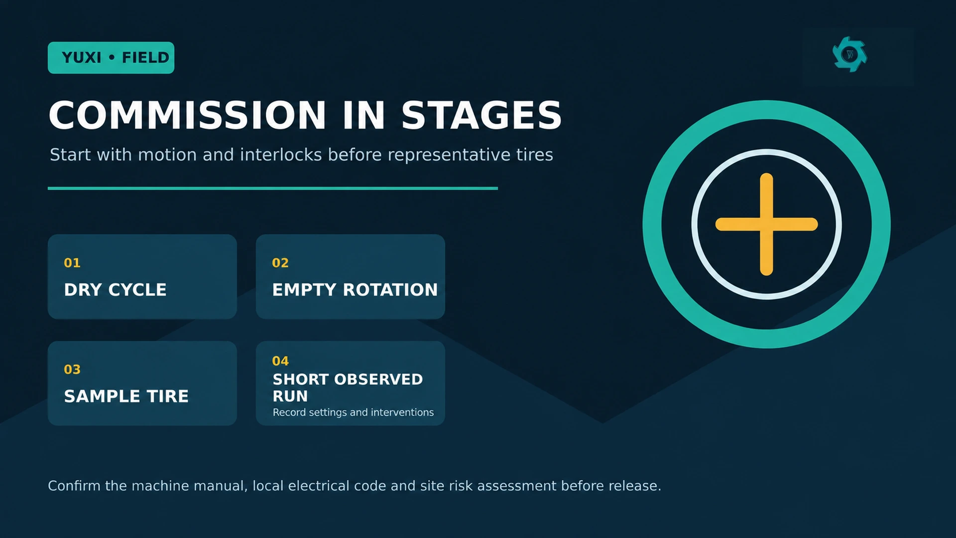
- Dry cycle: run the permitted motions without a tire. Watch for guard interference, cable movement, vibration and unexpected travel limits.
- Empty rotation: observe the table through a complete cycle and confirm braking or stopping behavior.
- Sample tire: use an agreed tire within the normal feed range. Check clamp stability, cutter entry, cut continuity and the safe removal of carcass and bead section.
- Short observed run: process a defined sample and record cycle time, interventions, rejected tires and cutter condition.
Do not advertise a throughput rate based on the fastest isolated tire. Record both elapsed time and cutting-cycle time, plus loading, repositioning, inspection and clearing time. This is the number that helps an operator match the bead cutter to a tire cutting machine or the next size-reduction step.
5. Define what the cutter is—and is not—proving
The purpose of this station is to cut through the sidewall/bead area and separate the bead ring or bead-sidewall section from the tire body. It is not normally a complete steel-cleaning operation. If the business case relies on clean bead-wire recovery, plan the separate downstream handling route and distinguish it from a tire wire drawing machine, which has a different removal action and output condition.
Likewise, confirm what the downstream shredder accepts. Pre-cutting reduces the concentrated bead-ring challenge, but it does not remove every reinforcing wire in the carcass. The next equipment should be selected for its own feed envelope.
6. Handover: leave the operator a usable record

The handover sheet should contain the installed model and serial number, as-built electrical data, anchor and leveling confirmation, guard/interlock test results, representative tire description, cutter setting, observed cycle and elapsed times, cut-quality observations, lubrication points, spare-cutter part number and any open corrective action. It should name who may alter cutter settings and who may authorize restart after a jam or maintenance intervention.
Installation mistakes that create avoidable restarts
- Fixing the layout around the bare machine: leaves no practical tire staging or discharge area.
- Testing only with easy tires: makes a later truck-tire problem look like a sudden defect.
- Counting only machine-on time: hides the labor and handling time that constrains the line.
- Skipping a no-load direction check: can turn a wiring error into a cutting or guarding incident.
- Combining bead rings with general scrap immediately: removes the chance to inspect whether the cut is doing what the project needs.
7. Add an installation datum sheet—not just a checklist
A simple handover statement does not let a later technician distinguish between a changed tire mix, an altered cutter setting and a shifted foundation. A datum sheet gives the station a repeatable starting point. It is particularly useful after a site move, a cutter replacement or a period in which the operator has been compensating for a poor cut by changing clamp pressure.
| Datum | How to establish it | Why it matters later |
|---|---|---|
| Frame level at four named points | Measure after anchor tightening; note instrument and date | Separates a foundation/anchor change from a cutter problem |
| Representative tire envelope | Record rim diameter, outside diameter, construction and condition | Prevents an atypical tire becoming the unspoken “standard” |
| Clamp reference | Document the approved adjustment position for each tire family | Reduces trial-and-error loading on the next shift |
| Cutter reference | Record cutter ID, installed orientation and initial setting | Makes wear and setting changes traceable |
| Discharge route | Photograph the normal locations for carcass and bead section | Reveals when material handling, not cutting, is slowing the line |
Keep these as observed installation values, not universal tolerances. The permitted level, cutter position and anchor torque must come from the machine documentation and the site’s engineering requirements. The value of the datum sheet is comparison: after an upset, the team can see what changed before it starts adjusting the machine.
8. Use a three-tier tire trial, not one “good” test tire
A successful cut on a clean, round passenger tire proves very little about a recycling yard. For commissioning, divide the agreed feed into three visible groups: a normal tire, a hard-but-accepted tire such as a heavier casing within the configured range, and a condition challenge such as a tire with modest deformation or adhered dirt that the line is expected to handle. Reject unsafe, unapproved or out-of-range tires rather than forcing them through to make the trial look comprehensive.
Compare the trial results by intervention count as well as minutes per tire. A setting that is marginally faster but needs the operator to restrain the tire, reposition a bead section or clear a poor cut is not the robust commissioning setting. This turns installation into a design input for the labor plan and helps decide whether the station should feed a tire-derived fuel preparation line continuously or in batches.
9. Diagnose cut anomalies by their first visible symptom
| First symptom | Check before changing the cutter | Evidence to retain |
|---|---|---|
| Tire walks or tilts | Centering, clamp contact, tire deformation and table level | Photo of the loaded tire and clamp setting |
| Cut starts clean then wanders | Cutter support, loose fasteners, table runout and bead geometry | Marked start/finish positions and no-load observation |
| Repeated incomplete section | Approved cutter setting, tire-family range and cutter condition | Three sample cuts from the same group |
| Cycle time rises without an alarm | Loading path, bead-section discharge congestion and operator movements | Elapsed-time video, not only controller time |
| Abnormal noise or vibration | Stop, isolate and inspect against the manual; do not “run it in” | Time, operating state and inspection result |
This matrix avoids a common failure mode: using cutter adjustment as the answer to every bad result. Many cutting symptoms begin with tire condition, clamping or a changed operating boundary. Any inspection, jam clearing or cutter intervention must follow the site’s hazardous-energy procedure before a person reaches into the work zone.
The quality of an installation is often revealed after the first abnormal stop. Define who can reset an emergency stop, who can clear a jam, who can change cutter settings and who signs off after maintenance. Record the trigger for escalation: for example, a changed cutter path, missing guard hardware, repeat incomplete cuts, movement at the base, or unexplained vibration. This simple division prevents a temporary workaround from becoming the production standard.
11. Calculate the station’s real operating rhythm
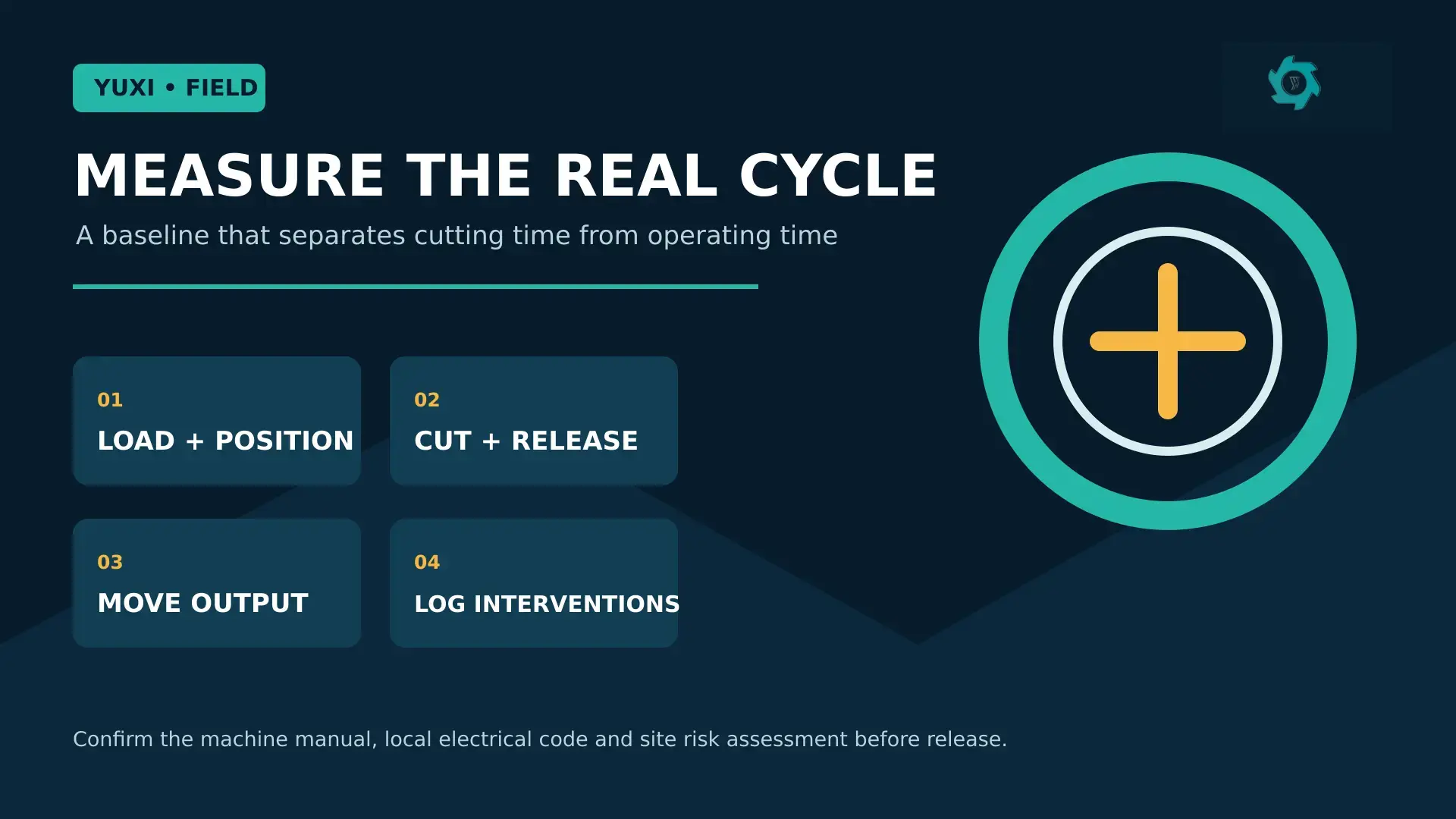
Nominal tires per hour is a weak installation metric because a bead cutter does not work in isolation. A practical baseline separates the total observed time into four elements: loading and positioning, cutting and release, output movement, and interventions. The total is the planning cycle. It is the number that determines whether a downstream machine waits for feed, a yard operator becomes the bottleneck, or bead sections accumulate in the wrong place.
For example, record 20 consecutive representative tires after the operator is familiar with the station. Calculate the median elapsed cycle rather than relying on the fastest run; then report the range and the number of interventions. The median prevents one very easy tire from setting an unrealistic expectation, while the range shows whether the site is operating inside a controlled window. Do not publish the result as a machine specification unless the test boundary, tire mix and operating arrangement are all stated.
12. Establish a seven-day startup baseline
The first accepted cut is not the end of commissioning. The first production week reveals cable routing that rubs only after repeated movement, bead-section containers that fill earlier than expected, and tire families that consume disproportionate operator time. Keep a short startup log for each shift. The log should separate planned changes from deviations and distinguish a quality observation from a safety-related stop.
| Daily field measure | Why it is more useful than a total count | Decision it supports |
|---|---|---|
| Representative tires completed | Connects output to a recorded tire family | Confirms the real feed envelope |
| Median elapsed cycle and range | Shows stability, not merely a best run | Sets a defensible line-planning rate |
| Interventions by type | Separates loading, cut, discharge and inspection losses | Prioritizes layout or setting changes |
| Cut-result exceptions | Keeps quality evidence tied to feed condition | Defines escalation criteria |
| Guard/interlock exceptions | Prevents production pressure from normalizing a workaround | Requires corrective action before continued operation |
At the end of the week, review patterns rather than averages alone. If time is lost mainly between cycles, adjust staging or collection. If it is lost during the cut, compare tire family, clamp reference and cutter condition before changing any setting. If the cause cannot be established, hold the approved baseline.
13. Treat every production change as a small controlled experiment
Commissioned settings should not drift because an operator is trying to make one difficult tire pass faster. When the tire family, cutter, clamp reference, table service, electrical work or downstream arrangement changes, create a one-page change card. State what changed, why it changed, who approved it, which representative tires will be checked, what result would trigger reversal, and what evidence will be kept. This is light enough for a small plant but prevents the loss of the original installation baseline.
The most valuable result is often a decision not to change the machine: an out-of-range tire can be isolated for a different route, while a verified station continues operating within its documented envelope. That protects both the equipment and the credibility of the reported operating rate.
FAQ
Does a bead cutter need to be anchored?
Follow the supplied anchor plan. A suitable, level base and correct anchoring help control movement and preserve alignment during repeated cycles.
What should be checked before the first tire is cut?
Verify the electrical supply and rotation, isolation method, guards, emergency stops, interlocks, level, anchors, cutter path and tire clamp using the supplier’s instructions.
How should the first production test be measured?
Use representative tires and log both elapsed and cutting-cycle time, plus loading, adjustments, stops, rejects and the cut condition.
Can the bead section go directly to a shredder?
That depends on the downstream equipment’s documented feed allowance. Keep bead sections separate until the intended processing route and safety controls are confirmed.
Plan A Safer Bead Cutting Station Before Delivery
Send your tire sizes, bead treatment goal, site layout, power supply and downstream receiving route. YUXI can help match the bead cutting machine installation boundary, commissioning checks and handover records to your plant plan.
Engineering References
- OSHA 1910.147. Control of hazardous energy.
- OSHA 1910.212. General machine guarding.