




A primary tire shredder and a secondary shredder are separated less by machine name than by the condition of the material they are expected to handle. The first stage has to take whole tires or approved pre-cut sections and turn them into feed that can move through the rest of the line without constant intervention. The second stage should receive material that is already under control and reduce it only as far as the next process needs. For project design, the most useful document is the handoff specification between the two machines: size and shape limits, bead-rich pieces, loose wire, contamination, normal mass flow and short surges.
Two-stage layouts are easy to draw. The first shredder sits ahead of a conveyor, the second machine follows, and the whole line may be labeled with one capacity number. That neat drawing can hide a serious problem: the two machines may have been selected around different assumptions.
A primary shredder might be quoted on whole passenger and truck tires. A secondary machine, meanwhile, may have been tested on clean, pre-shredded chips. Both suppliers can honestly print the same tonnes-per-hour number and still be describing very different duties. The gap only becomes visible after commissioning, when the first machine sends material the second machine was never expected to receive.
That is why this comparison starts with the material between the machines, not with motor power or model names. The YUXI tire shredder machine page covers the front-end role of whole-tire shredding. Here, the question is narrower: where should that front-end duty stop, and what must be true before a later reduction stage takes over? FHWA scrap-tire guidance has long described primary and secondary shredding as separate size-reduction stages, which is useful process context even though its historical size examples should not be treated as modern purchase specifications.[1]
The Primary Stage Has to Tame the Tire Before Anything Else
Whole tires are awkward feedstock. They roll, flex, spring back, carry concentrated steel in the bead, and do not always enter the cutting chamber in the same orientation. One tire may drop flat. The next can lean against the hopper wall. A truck tire may arrive after a run of passenger tires and change the load in one bite.
That makes the primary shredder responsible for more than cutting. It has to break the ring geometry and turn an unstable object into pieces that conveyors, screens and downstream machines can handle repeatedly. Hopper shape, cutter engagement, reducer torque and shaft speed all influence that job, but the real test is what comes out.
Long flexible strips are a good example. They may not be especially heavy, yet they can bridge a chute or span the inlet of the next machine. Bead-rich chunks create the opposite problem. A compact piece can look small in a sample while still carrying a local steel concentration that produces a hard bite downstream.
Control behavior belongs in the same discussion. Automatic reverse is useful when a difficult section stalls the shafts. Frequent reversing on ordinary feed is different. It can point to poor cutter engagement, excessive feed, worn knives or a material mix that is outside the expected operating window. A reverse counter is therefore more useful as a trend than as a simple “machine recovered successfully” message.
The first stage is doing its job when it removes the worst variability from the tire stream. That does not mean every piece has to be identical. It means the remaining variation is narrow enough for the next machine to accept without operators constantly slowing the feed, separating pieces by hand or clearing avoidable jams.
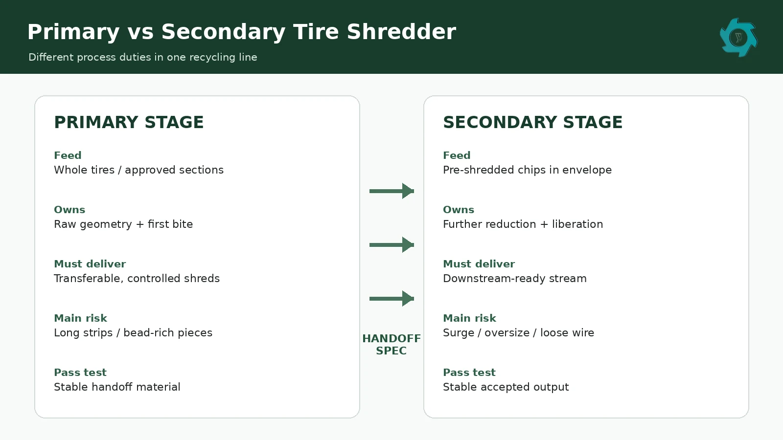
The Transfer Point Is the Real Specification
A single output number rarely describes the primary stage well enough. “100 mm output” may refer to a screen opening, a nominal chip size, an average or a maximum dimension. It says nothing about long strips, dense bead sections or loose wire. Those details are often what decide whether the second machine runs smoothly.
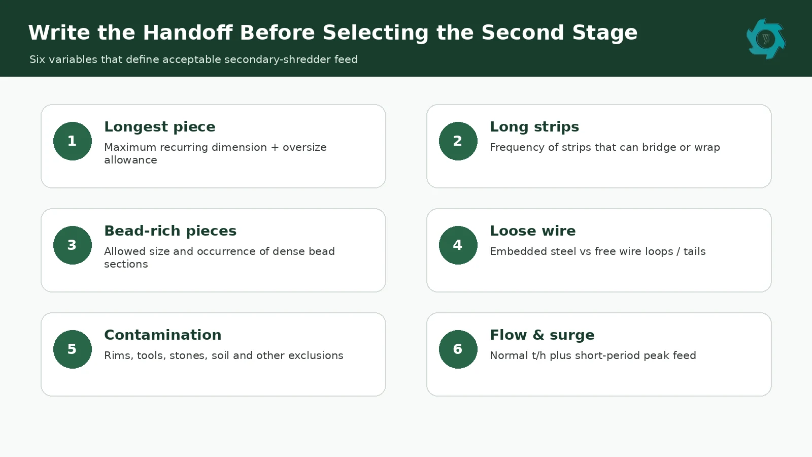
For project work, it is better to write a short handoff specification. The document does not need laboratory language. It only needs rules that can be checked the same way during quotation, factory testing and commissioning.
Start with geometry. Record the largest recurring piece or define an agreed sampling rule. Treat long strips separately because they behave differently from compact chips. Bead-rich pieces deserve their own limit as well. If free wire is unacceptable, say so directly rather than assuming everyone uses the same definition of “shredded tire.”
Mass flow also belongs in the handoff. The first machine may discharge in bursts even when the hourly average looks stable. The secondary machine sees those bursts as real load. A short surge can matter more than a neat average when the inlet or intermediate buffer is small.
| Handoff item | What to record | Why it matters downstream |
|---|---|---|
| Piece geometry | Longest recurring dimension and agreed oversize allowance | Long pieces can bridge, fold or span the inlet |
| Long strips | Count or frequency in a defined sample | Flexible strips can wrap or create irregular bites |
| Bead-rich pieces | Permitted condition and approximate frequency | Concentrated steel changes local cutting resistance |
| Loose wire | Embedded only, limited free wire, or no free wire | Free wire can wrap shafts, conveyors and screens |
| Mass flow | Normal accepted rate plus expected short surge | The next stage must handle both average flow and pulses |
| Foreign material | List prohibited contamination | Protects cutters and removes ambiguity during FAT |
Capacity accounting should use the same boundary. Material that is still circulating in the first-stage loop is not yet available to the second machine. The separate YUXI capacity guide explains the difference between fresh feed, internal circulation and accepted output. In a two-stage line, the relevant first-stage capacity is the mass that actually reaches the transfer point in the agreed condition.
Contamination needs its own line in the specification. Rims, tools, stones and heavy metal parts are obvious exclusions. Mud, water and embedded debris are less dramatic, but they can still change friction, screening and feed behavior. A clear list of prohibited material gives operators something useful to work from after the plant is handed over.
Secondary Reduction Works Only When Upstream Variation Is Under Control
Once the tire ring has been broken, the nature of the work changes. The next machine should be reducing pre-shredded material, not repeatedly solving whole-tire intake problems. In many mulch and crumb lines that second duty is handled by a rasper. The YUXI rasper guide covers how that equipment works, so the important point here is its inlet condition.
A secondary machine that runs steadily on compact tire chips can become erratic when it receives half-tires, long sidewall strips or bead-heavy pieces. Operators usually notice this before the production report does. Current begins to jump, the feed conveyor stops more often, or someone starts spacing pieces by hand to prevent hard bites.
Steel exposure becomes more important at this stage as well. Cutting does not remove steel by itself; it opens the rubber matrix so magnetic separation can recover more of the reinforcement. The U.S. EPA describes crumb-rubber processing as progressive size reduction followed by separation steps that include magnetic steel removal and air separation of fabric.[2] The order matters. A magnet cannot recover steel that remains locked inside large rubber sections.
When the secondary stage is blamed for low output, look upstream before increasing motor size. A machine fed outside its agreed envelope may be spending capacity on irregular intake instead of controlled reduction. That is a line-design problem, not automatically a machine-size problem.
Watch the Buffer, Not the Brochure
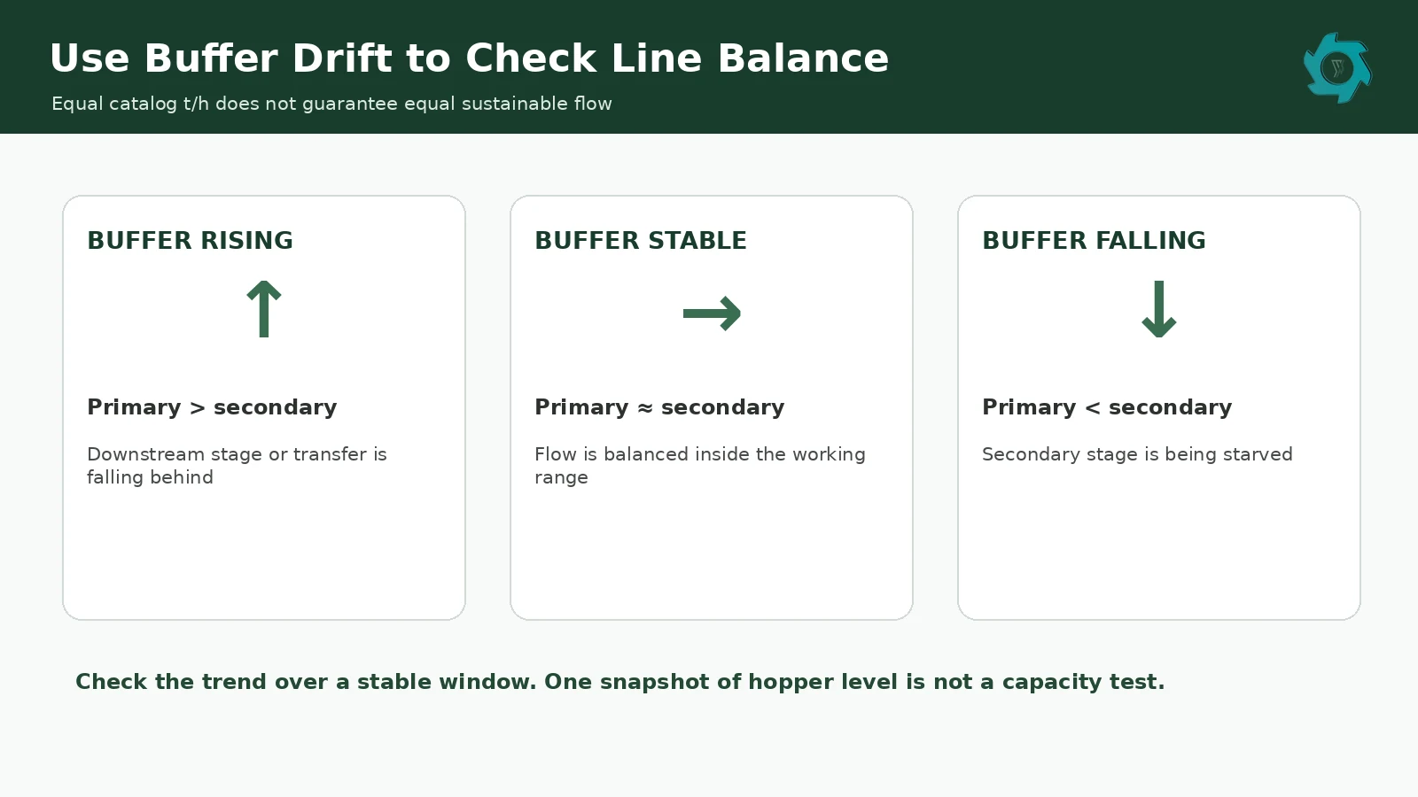
Two machines rated at 5 t/h are not automatically balanced. The first stage may discharge in pulses. It may also be recirculating oversize. The second stage can have its own return load and may consume material more steadily. The intermediate buffer is where those differences become visible.
A buffer that keeps climbing means downstream consumption is below upstream delivery under the current conditions. A buffer that repeatedly empties tells a different story: the second stage is being starved. Neither pattern is fixed by pointing to matching catalog capacities.
There are several ways to observe the trend. A weigh belt is useful, but level sensors, a calibrated hopper volume or a simple recorded level scale can also show inventory drift. The measurement only needs to be consistent enough to compare one operating period with another.
Mixed tires make the point clear. A run may be mostly passenger tires with a truck tire entering every few minutes. The primary shredder handles the average rate, then releases a larger burst after the heavier tire passes. A small buffer can absorb that pulse. A poorly controlled transfer conveyor may push it directly into the secondary inlet.
Reserve capacity still matters, but there is no universal percentage that fixes every line. The required margin depends on tire mix, recirculation, maintenance condition, buffer size, screen settings and how much the process changes between normal and difficult feed.
One Stage Can Be Enough
Adding a second shredder is not automatically better engineering. Coarse volume reduction and some TDF duties can be completed in one stage when the first shredder makes the accepted product at the required rate. A second machine would then add wear parts, controls, conveying and maintenance without creating useful value.
The situation changes when the final product needs tighter reduction or stronger steel liberation. Trying to remove the second stage while keeping the same downstream requirement usually pushes more recutting back into the primary shredder. Return load rises, accepted output can fall, and the front-end machine is now being asked to accept whole tires and perform a job that was originally separated for a reason.
The detailed relationship between screen opening, recirculation and accepted output is covered in YUXI’s screen and recirculation guide. For this article, the simpler test is enough: if deleting the second machine leaves the same amount of cutting and liberation work somewhere else in the line, the process has not actually been simplified.
Controls and Wear Show Where the Line Is Drifting
A healthy transfer point is not maintained by mechanical design alone. The controls need to stop one stage from creating a problem for the other. High buffer level, sustained downstream load, conveyor stops and repeated reversals are useful signals because they describe what is happening at the boundary between machines.
When the secondary feed path stops, upstream discharge should not continue indefinitely. A high-level signal may slow or stop fresh feed. Low level can request more material before the downstream machine spends long periods empty. Sustained high load on the secondary drive can reduce feed before the line reaches an overload trip.
Knife wear changes these signals gradually. At the primary stage, worn cutters may show up as poor hook engagement, more folding, extra long strips or a rising reversal count. The machine still turns, so the change can be missed if maintenance is based only on visible damage.
Downstream wear can look different. More cutting events per tonne make edge condition and clearance increasingly important. As knives lose sharpness, the machine may run hotter, hold more material in circulation, or expose steel less effectively. Accepted output drifts even though the motor is still operating.
For this reason, blade life should not be recorded as hours alone. Note the tire mix, output rule and the condition that triggered adjustment, rotation, sharpening or replacement. One plant may change knives when product quality starts to drift; another may run until wear is obvious. Those are not comparable definitions of service life.
Mixed Tire Feed Exposes Weak Stage Boundaries
Passenger and truck tires can share a line, but the heaviest recurring tire usually drives the front-end requirement. Larger tires change intake geometry and local cutting resistance. Their bead and belt packages also influence the type of pieces that leave the primary chamber.
Downstream equipment should not have to “know” whether a chip came from a passenger tire or a truck tire. If both materials arrive inside the written handoff envelope, the second stage can treat them as controlled feed. When truck-tire sections arrive as dense bead blocks or long sidewall strips, the variation has leaked across the boundary.
OTR material makes the same lesson more obvious. Many OTR tires are too large for a standard whole-tire intake and need separate cutting or preparation. Sending occasional oversize sections forward and relying on the secondary machine to absorb the exception is not a stable operating method.
Test the Two Jobs Separately Before Calling the Line Complete
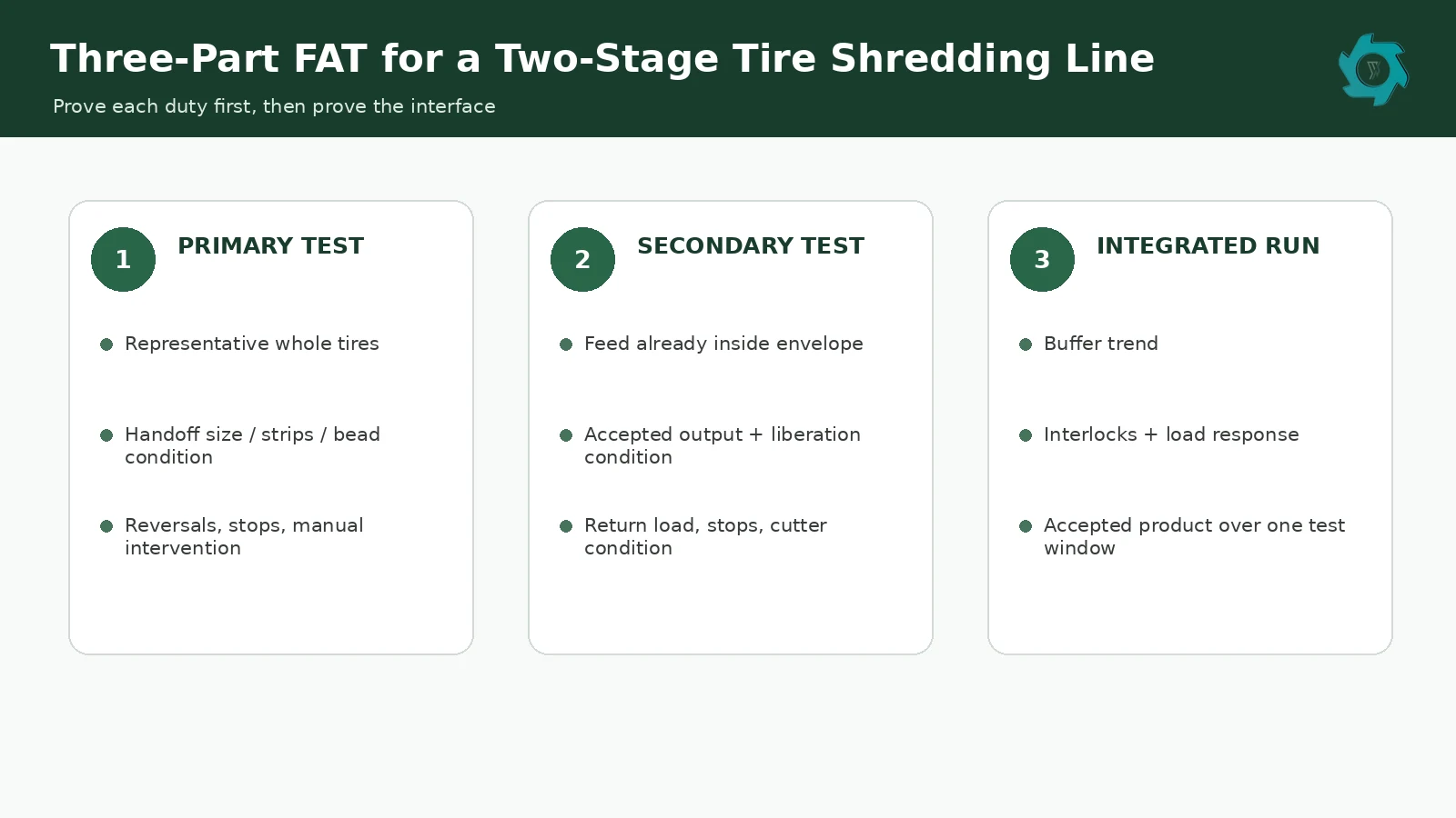
An integrated factory test is necessary, but it should not be the first time anyone asks whether the individual stages are doing what was promised. Testing each duty first makes a later line-level problem much easier to trace.
Run the primary stage on the quoted tire mix
Use representative feed, including the difficult items that are normal for the project. Record feed mass, operating time, reverse events, manual interventions and stops. Then inspect the discharge against the handoff rule. A pile that “looks about right” is weak evidence when the second-stage warranty depends on what is in it.
Feed the secondary stage with material that already passes the handoff rule
This isolates the second machine. If steel liberation is part of its duty, inspect that condition along with size. Use a sampling method agreed before the test rather than a clean handful chosen from the conveyor.
Connect the line and watch inventory as well as tonnage
During the integrated run, track buffer level, upstream feed, accepted product, downstream load and stop events. A line that reaches target tonnage only because an operator constantly adjusts conveyor speed by feel is not yet a stable automatic process.
Jam clearing and service access should also be included in the acceptance discussion. Tire shredders store electrical and mechanical energy, and some systems also include hydraulic energy. OSHA’s lockout/tagout standard addresses hazardous-energy control during covered servicing and maintenance work.[3] Site procedures, guarding and isolation points must be established by the employer and qualified personnel.
What to Put in the RFQ
A useful RFQ does not need fifty pages. It needs enough detail to prevent different assumptions from hiding behind the same words. The most important items describe the feed, the transfer point and the product boundary.
| RFQ item | Information to provide |
|---|---|
| Feed mix | Passenger, truck, bus, agricultural or OTR; approximate share by mass; largest recurring tire |
| Feed condition | Whole, debeaded, sidewall removed, pre-cut, dirty, wet or mixed preparation |
| Primary-stage output | Piece geometry, long-strip rule, bead condition, loose-wire condition and contamination limit |
| Secondary-stage duty | Required output range, oversize allowance, steel-liberation expectation and next process |
| Capacity | Accepted t/h and whether the basis is running time or elapsed shift time |
| Controls | Buffer-level signals, interlocks, load feedback, stop sequence and required plant communications |
| Maintenance | Knife access, screen access, lifting provisions, wire-cleaning points and service space |
Add the local voltage and frequency, expected operating hours, floor-space limits and any restrictions on foundations, crane access or building height. These details are basic, but they affect motors, controls and layout. They are cheaper to resolve before the equipment arrangement is frozen.
The same RFQ should state how FAT will be judged. If capacity is critical, specify accepted output rather than just fresh feed. If long strips or bead-rich pieces are a concern, define how they will be sampled. A test criterion that cannot be checked in the factory will not become clearer after installation.
The Final Product Decides How Far Reduction Should Go
Coarse volume reduction may stop after the primary stage. Some TDF specifications can also be reached there when the receiving customer accepts the resulting chip condition. Once the product moves toward wire-free mulch, crumb or powder, the process usually needs tighter control.
For mulch, the second stage often earns its place by improving size consistency and exposing more steel for recovery. The YUXI wire-free mulch plant shows that route. Crumb production goes further; a rubber crumb plant needs controlled feed before granulation and finer separation.
The selection question is therefore practical. Look at the material before the machine, then at the condition required after it. If the job is still “accept whole tires and make them manageable,” the machine is carrying primary-stage duty. If the feed is already pre-shredded and the task is controlled reduction or liberation for the next process, the duty is secondary. When neither description fits, the process boundary still needs work.
One Last Check Before Approval
Put the two machine data sheets next to each other and ignore the model names for a moment. Read only the discharge condition of the primary stage and the inlet condition of the secondary stage. Do they describe the same material?
A gap is easy to spot once you ask that question. The first sheet may allow long bead sections while the second assumes compact chips. One capacity figure may be based on fresh feed while the other is based on screened accepted output. One test may use passenger tires while the project depends on a mixed truck-tire stream.
Those mismatches are cheap to fix on paper and expensive to discover during commissioning. A good two-stage line does not need identical machines or matching catalog ratings. It needs a measurable boundary between jobs. Once that boundary is clear, model selection, buffer sizing, control logic and FAT become much easier to agree on.
FAQ
What is the practical difference between a primary and secondary tire shredder?
The primary machine accepts whole tires or approved pre-cut sections and removes the difficult ring geometry. The secondary machine receives pre-shredded material that already fits a narrower inlet condition, then continues reduction or steel liberation for the next process.
Can one tire shredder replace both stages?
Yes, when the required product is coarse enough and the first stage can make it at the required accepted capacity without excessive recirculation. If substantial further reduction or steel liberation is still required, that work remains in the process even if the second machine is deleted.
What should be specified between the two machines?
Use a handoff specification covering piece geometry, long strips, bead-rich pieces, free wire, contamination, normal mass flow and short surges. The rules should be simple enough to check during factory testing and site commissioning.
Do the primary and secondary shredders need the same tons-per-hour rating?
No. Catalog ratings can use different feed, output and time bases. Sustainable accepted flow through both stages and stable intermediate-buffer behavior are more useful for line balancing.
Does the secondary shredder remove steel?
The cutting stage can expose or liberate steel from rubber, but magnetic or other separation equipment performs the actual recovery. Liberation and separation should be specified as related but separate duties.
What should be checked during a factory acceptance test?
Test the primary stage on representative tires, inspect its discharge against the handoff rule, test the secondary stage on compliant feed, then run the connected line while tracking accepted output, buffer trend, load events, reversals, stops and product condition over the same agreed test window.
Configure the Two Stages Around Your Real Tire Mix
Send the largest recurring tire, passenger/truck mix, any pre-cutting or debeading, required final product and accepted capacity. YUXI can match the primary shredder, secondary reduction stage, buffer, conveying and separation equipment around one defined material handoff.
Engineering References
- Federal Highway Administration — scrap tire guidance. Used for historical process context on primary and secondary shredding.
- U.S. Environmental Protection Agency — tire crumb Q&A. Describes progressive size reduction together with steel and fiber separation.
- Occupational Safety and Health Administration — 29 CFR 1910.147. Reference for hazardous-energy control during covered servicing and maintenance.