




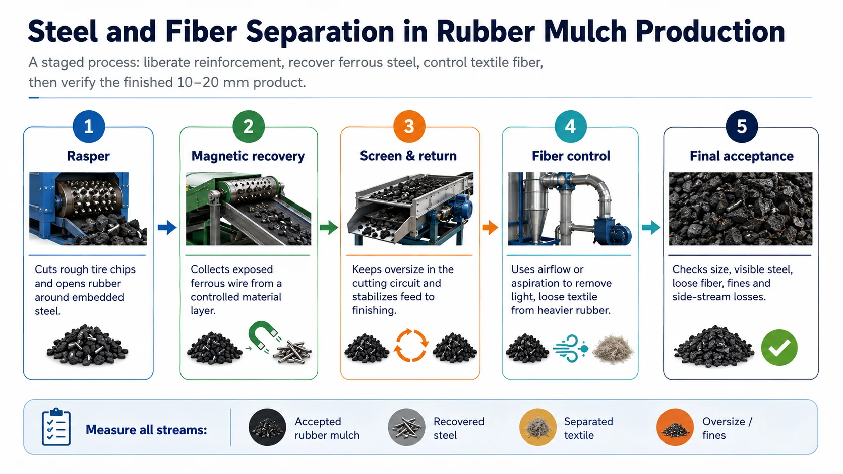
A magnet can be pulling wire all day while the finished rubber still fails inspection. We have seen the opposite problem as well: the fiber system looks very active, the collection bags fill quickly, yet a surprising amount of good rubber is leaving with the fluff. Both situations come from treating “separation” as one step instead of several connected duties.
Inside a tire, steel and textile are not loose contaminants sprinkled through rubber. They are reinforcement materials built into the structure. Rasping must first expose them. A magnetic separator can then recover ferrous wire. Airflow can remove loose textile only after cutting has created a particle-size and density difference that the separator can use. Screening, burden depth, return load and dust handling decide whether those stages remain stable over a full shift.
Why Steel and Fiber Need Separate Separation Stages
Steel separation in rubber mulch production has two boundaries: the tire rasper must liberate embedded steel, and the magnetic system must recover the released ferrous wire. Textile fiber is nonmagnetic. It is normally controlled later with airflow, aspiration, screening and collection equipment operating on a more uniform rubber fraction.
The useful process sequence is therefore not “shred, separate and finish.” It is: prepare a controlled rasper feed, cut until reinforcement is exposed, recover ferrous steel from a manageable material layer, stabilize the accepted size range, remove loose textile without carrying excessive rubber, and verify all product and by-product streams during a representative test.
Steel and Textile Fiber Behave Differently After a Tire Is Cut
Passenger, light-truck and truck tires do not contain one standard reinforcement package. Steel may appear in bead bundles, tread belts and, in some truck constructions, body plies. Textile reinforcement can include polyester, nylon or other fibers. The mix entering a recycling line therefore changes with the incoming tire categories and with any front-end bead treatment.1
The U.S. EPA describes recycled tire-rubber production as a staged size-reduction process in which steel belt material and fabric are separated with magnetic separators, air classifiers or other separation equipment.2 That distinction is the basis of the line design:
Ferrous steel
Magnetically responsive after it has been sufficiently exposed. It may appear as long wire, short fragments, rubber-coated strands or steel still locked inside chips.
Textile fiber
Nonmagnetic and comparatively light when loose. It may remain embedded, appear as strands, or break into fluff and dust that moves with air.
Rubber
Heavier than loose fiber but variable in shape. Small thin rubber pieces can become airborne and be lost when airflow is too aggressive or the feed contains excessive fines.
This is why adding a “separator” to a quotation is not enough. The quotation should identify which fraction the equipment targets, the feed size it receives, the expected burden depth, the side stream it creates and the test used to judge both cleanliness and rubber loss.
Steel Separation Starts Inside the Rasper, Not at the Magnet
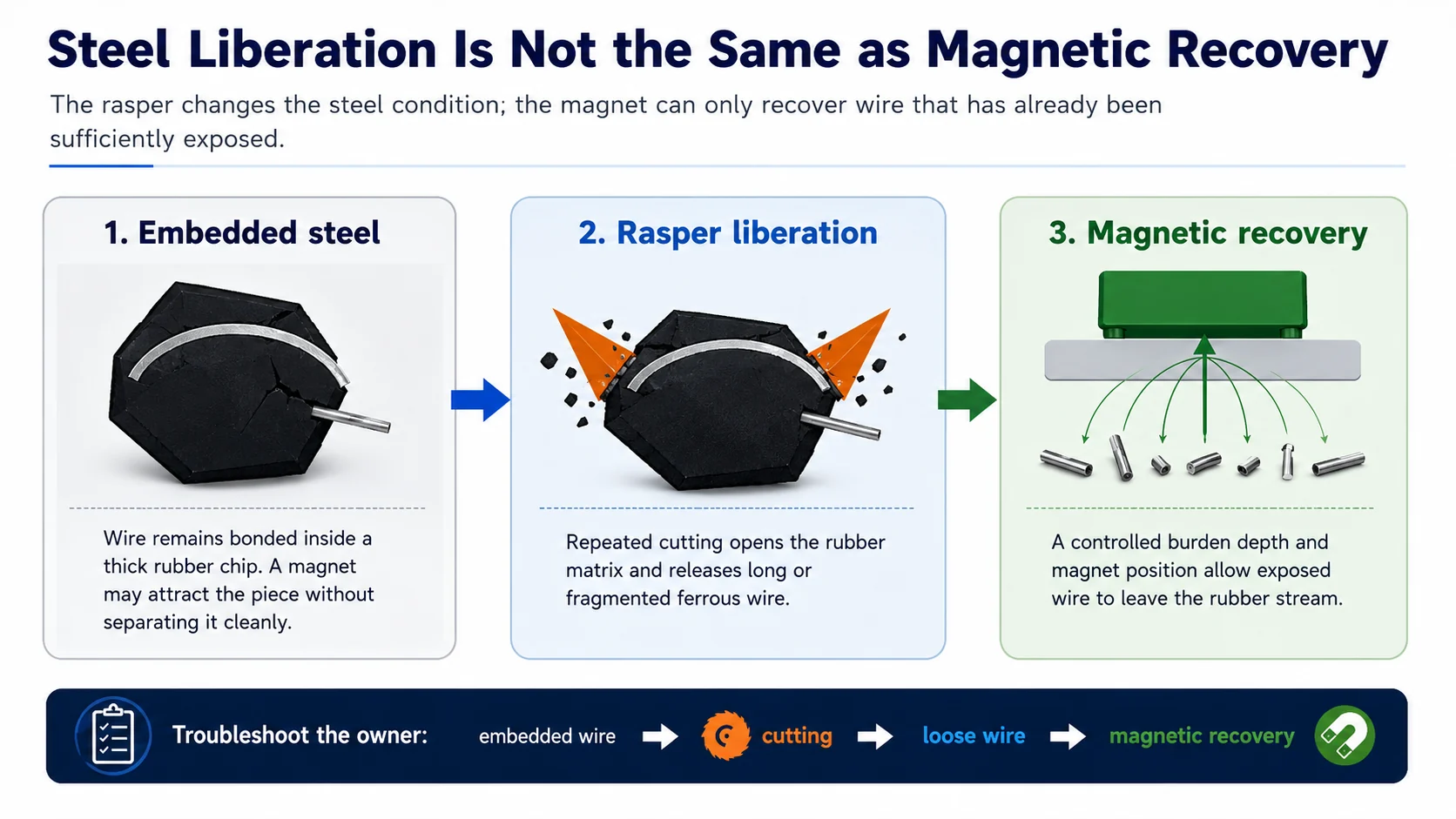
A tire chip with steel fully encapsulated in rubber is not yet a magnetic-separation problem. It is a liberation problem. The magnet may attract the entire rubber-steel piece, but that creates a dirty recovered-steel stream and removes saleable rubber. It may also fail to lift the piece when the rubber mass, material layer and conveyor geometry keep the steel too far from the magnetic field.
What improves liberation
Liberation improves when rough chips enter within the accepted size and shape envelope, knives remain in the approved condition, cutting gaps are maintained, the screen retains pieces that still need work and the return loop actually brings oversize back for another controlled pass. Tire construction also matters. A truck-heavy mix may expose long, tough steel cords differently from a passenger-tire mix.
What a liberation check should inspect
Do not look only at the wire pile. Inspect both sides of the split. Recovered steel carrying thick rubber indicates that the line is removing product with the metal. Accepted rubber containing thick chips with internal or protruding steel indicates insufficient cutting, an unsuitable screen-return condition or a sampling rule that is too weak to detect the defect.
In practice: when visible wire suddenly increases, check whether the defect is embedded, exposed or loose. Those three appearances can lead to three different adjustments. Increasing magnet duty will not correct steel that remains locked inside rubber.
How Magnetic Steel Recovery Works in a Rubber Mulch Line
After rasping, the discharge is a mixed stream of rubber chips, loose steel, rubber-coated wire, textile and off-size material. The magnetic separator should see this material as an even, shallow and predictable burden. A strong magnetic field cannot compensate indefinitely for a deep pulsing pile or a conveyor carrying tangled wire under thick rubber.
| Magnetic-recovery variable | Why it matters | Typical symptom when unstable |
|---|---|---|
| Burden depth | Steel at the bottom of a deep rubber layer is farther from the field and may be shielded by material above it. | Loose wire appears intermittently in finished mulch, especially during feed surges. |
| Belt speed | The separator needs enough exposure time to attract and transfer irregular wire without creating a bottleneck. | Higher throughput causes carryover even though the magnet setting is unchanged. |
| Magnet position and gap | Field strength at the material surface changes with distance and the trajectory of the lifted steel. | Wire is attracted but drops back into the product stream. |
| Wire shape and entanglement | Long cords can hook into rubber or each other; short fragments behave differently from bundles. | A clean sample is followed by sudden nests of wire downstream. |
| Feed presentation | Spreaders, transitions and chute design determine whether the burden is centered and evenly distributed. | One side of the product belt is cleaner than the other. |
| Number of magnetic passes | A first stage can remove the bulk wire; a polishing stage can target remaining loose ferrous material after size control. | A single magnet must be set aggressively and carries too much rubber with the steel. |
The practical goal is not simply the greatest possible attraction. It is a stable split: steel leaves through the metal stream, rubber remains in the product stream, and the equipment can handle long wire without wrapping, plugging or unsafe manual intervention. A second magnetic stage can be justified when the finished-product rule is tighter, but it should not hide poor liberation upstream.
How Textile-Fiber Separation Works After Steel Recovery
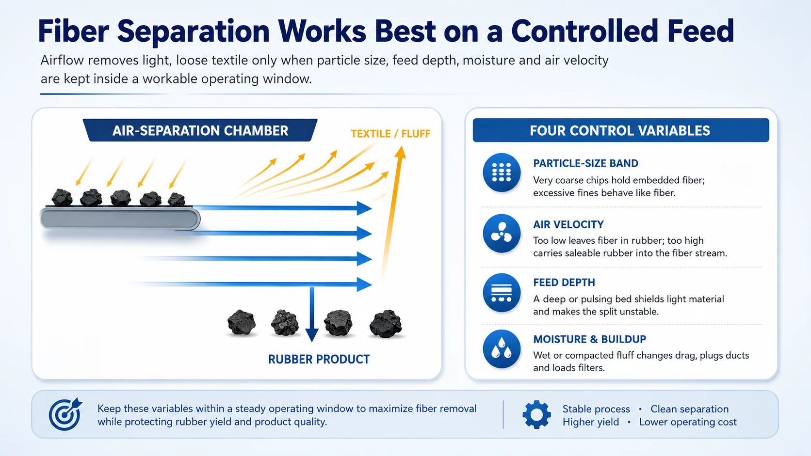
Textile fiber becomes easier to separate as cutting exposes it and the product moves toward a controlled size range. Loose fiber has a high surface area relative to its mass, so an air stream can lift or redirect it while heavier rubber follows another path. The same principle can also lift small rubber fines. That is why fiber separation is a control problem, not a simple “more air equals cleaner product” adjustment.
Particle size controls the density split
Large rubber chips can still contain embedded textile that no air separator can remove. At the other extreme, thin rubber slivers and fines can move with fluff and reduce rubber yield. Screening before the main fiber-control stage often gives the air system a more predictable feed, while oversize returns for additional cutting.
Feed depth and pulsing affect the air path
A thin, even layer exposes more loose fiber. A deep surge can trap light material inside the bed and make the product alternately clean and dirty. If the upstream conveyor or screen discharges in pulses, changing the fan setting may only move the problem from one minute to the next.
Air velocity must balance cleanliness and yield
Too little airflow leaves loose textile with the mulch. Too much carries small saleable rubber into the light fraction. We normally recommend checking both streams after every meaningful adjustment. Looking only at the final rubber can produce an apparently clean product while the fiber bag quietly becomes a rubber-loss stream.
Ducts, cyclones and filters are part of separation performance
Airflow at the separator is not useful if ducts leak, a cyclone is overloaded or filters are blinded by fluff. Pressure changes and buildup alter the actual split. The collected textile stream also needs a handling route that prevents it from returning to conveyors or accumulating around ignition sources.
A Practical Steel-and-Fiber Separation Sequence
The exact order varies by equipment layout, but the engineering logic should remain clear. A typical whole-tire route is primary shredding, metered feeding to the rasper, bulk magnetic recovery, size classification with oversize return, optional magnetic polishing, fiber control on the accepted stream and final product collection. A module beginning with pre-shredded chips starts at the rasper.
| Stage | Incoming condition | Main duty | What should leave the stage |
|---|---|---|---|
| Primary shredder | Whole tires or prepared sections | Create a stable feed for secondary processing | Rough chips within the agreed rasper envelope |
| Tire rasper | Rough chips with embedded steel and textile | Reduce size and expose reinforcement | Mulch-size rubber, liberated steel, textile and oversize |
| Primary magnet | Rasper discharge in a controlled layer | Remove the bulk of loose ferrous wire | Recovered steel plus a rubber-fiber stream |
| Screen and return | Rubber, fiber and remaining off-size material | Stabilize the accepted range and return oversize | Accepted fraction plus a measured return stream |
| Polishing magnet, when required | More uniform accepted-size material | Capture remaining loose ferrous pieces | Lower loose-wire burden without excessive rubber loss |
| Fiber separator | Steel-controlled, size-controlled rubber with loose textile | Use airflow or aspiration to remove light fiber | Cleaner rubber plus a separately collected textile stream |
| Final sampling | Finished rubber mulch | Verify size, steel, fiber and yield | Accepted or rejected product lot with a recorded test basis |
The article on controlling 10-20 mm rubber mulch size explains screen openings, orientation effects and recirculation in more detail. For separation, the important point is that a more consistent size band makes both magnetic and pneumatic behavior easier to reproduce.
Layout principle: keep inspection and sample points after the rasper, after bulk magnetic recovery, at the accepted screen discharge, in the fiber side stream and at final product collection. Without those points, a failed product sample tells the operator very little about where the defect entered.
Operating Variables That Change Final Steel and Fiber Quality
Separation performance is connected to the whole line. A knife adjustment changes liberation. A screen change changes recirculation and particle shape. A higher feed rate changes burden depth at the magnet and residence time in the air separator. Operators should therefore change one variable at a time and keep a short record of the product response.
Tire mix
Passenger and truck tires can release steel and textile differently. Record the representative proportions used during testing instead of describing the feed only as “waste tires.”
Knife and gap condition
Dull or damaged cutting edges can increase thick chips, attached rubber on steel and unstable motor load. A sample may still look acceptable before the defect becomes consistent.
Screen and return rate
A tighter product range sends more oversize back. This can improve liberation but also increases cutting work and can overload the return conveyor or rasper.
Conveyor presentation
Uneven loading changes the distance between steel and the magnet, while pulsing changes the air-separation burden. Chute and spreader design therefore affect purity.
Fines generation
Fines can help release fiber but make the air split more difficult and increase dust collection duty. They must be measured as a product or loss stream.
Moisture and contamination
Wet fluff can agglomerate and plug ducts. Stones, rim pieces and other foreign metal can damage equipment and should be controlled at receiving.
On one export project, a clean hand sample created confidence during a short trial, but the longer run exposed a different problem: the return stream built up, burden depth increased, and loose wire began to appear after the line reached steady state. The lesson was not that the magnet had suddenly weakened. The line balance had changed.
Troubleshoot the Defect Before Changing the Separator
| Product or side-stream defect | First process questions | Useful corrective direction |
|---|---|---|
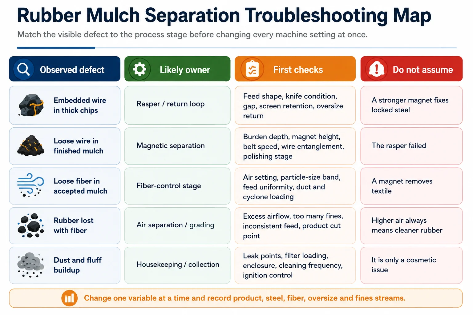
| Embedded steel in thick chips | Did feed size change- Are knives and gaps within the approved condition- Is oversize returning- | Restore liberation and recirculation before increasing magnetic duty. |
| Loose wire in final mulch | Is burden depth stable- Is material spread across the belt- Are long wire nests bypassing the field- | Stabilize presentation, adjust magnet position or speed, and evaluate a polishing stage. |
| Rubber attached to recovered steel | Is the steel insufficiently liberated, or is the magnet lifting composite pieces- | Inspect rasper output and screen retention; do not judge success only by steel mass. |
| Loose textile in accepted rubber | Is the feed-size band too broad- Is airflow low or pulsing- Are ducts and filters loaded- | Stabilize feed and collection, then adjust airflow with both streams under observation. |
| Too much rubber in the fiber fraction | Has airflow increased- Are fines or thin chips rising with the textile- | Reduce aggressive carryover, tighten grading or use a controlled second pass. |
| Dust and fluff around the line | Where are leaks and deposits forming- Is collection capacity matched to the generated fines- | Repair containment and cleaning practice; evaluate the dust hazard rather than treating it as housekeeping alone. |
Avoid simultaneous changes: changing rasper feed, magnet height, screen opening and fan setting at the same time may improve one sample, but it removes the evidence needed to repeat the result.
Capacity Must Be Measured at the Accepted-Product Boundary
A line can feed two tons per hour into the rasper and produce much less accepted mulch if oversize circulates heavily, steel carries rubber away, the fiber stream contains fine rubber or downtime is excluded. The useful commercial number is accepted finished product per productive hour under the agreed steel, fiber and size limits.
Fresh tire feed = accepted rubber + recovered steel + textile fraction + oversize inventory change + fines + rejects + unmeasured loss
That equation does not require laboratory precision during every shift. It does require enough weighing and recording to detect an impossible claim. If the reported accepted rubber plus steel and fiber exceeds the measured feed, the test basis is incomplete. If the fiber side stream is not weighed, an aggressive air setting can hide rubber loss. If return material is treated as fresh production each time it crosses a belt scale, apparent throughput can be exaggerated.
Report at least five rate numbers
- Fresh incoming feed within the declared test boundary.
- Accepted finished rubber mulch after all product checks.
- Recovered steel, including visible rubber carryover.
- Separated textile and fines, with an observation of rubber content.
- Oversize return rate or a calibrated trend showing whether the loop is stable.
The 0.5-10 t/h range on the
YUXI Tire Wire Free Mulch Plant
page should be treated as a configurable project range, not as a guaranteed accepted-product output for every tire mix. Final capacity should be confirmed against the representative feed, process scope, return load and finished-product acceptance boundary.
How to Test Steel and Fiber Separation During a Factory Acceptance Test
A clean handful collected after the operator reduces the feed is not a useful acceptance test. The complete line should reach steady state first. The return loop, magnet burden, fiber collection and discharge should all be operating as they will during the measured period.
1. Freeze the test conditions
Record tire categories and proportions, feed preparation, maximum rough-chip condition, rasper knife state, screen drawing, magnet arrangement, conveyor speeds, air-system settings, net runtime and permitted stops.
2. Sample over time and across the stream
Collect increments at regular intervals and from the full product width. Combine them into a composite sample. When particle-size distribution is part of acceptance, confirm the sieve method before testing.3 Although the EPA protocol concerns synthetic-turf crumb-rubber characterization rather than factory acceptance of coarse mulch, its use of multiple increments combined into a representative composite sample illustrates why one convenient handful should not represent a production run.
3. Classify steel defects separately
Record embedded steel, exposed steel and loose steel as different observations. A pass/fail rule may focus on exposed sharp wire, a measured metal limit or both. The rule should state sample mass, inspection method and what happens when one piece fails.
4. Define the textile check
A visual loose-fiber grade can be practical for some mulch markets, but it should include reference samples or photos. A mass-based method is stronger when the buyer requires a measurable limit. Embedded textile should not be confused with loose fluff that can be removed pneumatically.
5. Weigh the side streams
Recovered steel and textile are not only by-products. Their mass and condition explain product yield. Photograph rubber attached to wire and rubber carried into the fiber stream. Those observations are often more useful for commissioning than one headline purity percentage.
Acceptance statement example: “During a stated net run using the declared tire mix, the line shall produce the required mass of accepted 10-20 mm rubber mulch per hour. Composite samples shall meet the agreed size distribution, visible-steel rule and loose-textile grade. Steel, textile, fines, oversize return and rejects shall be recorded separately.”
Fiber and Rubber Dust Need an Engineering Safety Review
Fiber separation and repeated size reduction can generate fluff and fine rubber dust around screens, transfer points, ducts and collection equipment. OSHA’s combustible-dust guidance notes that finely divided solids, fibers and fines can create fire or deflagration hazards under some conditions, and it specifically includes tire and rubber manufacturing among industries where combustible-dust issues may be encountered.4
The correct design depends on the actual material and local rules. It may involve enclosure, source capture, bonding and grounding, suitable electrical classification, explosion protection, fire detection, housekeeping and a dust-hazard analysis by qualified personnel. A generic dust collector should not be treated as proof of compliance.
Maintenance isolation is part of separator design
Wire can wrap around shafts, screens can plug and fiber can accumulate in ducts. Access doors, cleanout points and magnet or conveyor service areas should be designed so operators can isolate hazardous energy before clearing material. The line proposal should identify the isolation boundary, not rely on reaching into a stopped machine.
Information to Send for a Steel-and-Fiber Separation Proposal
A useful inquiry describes the material at every handoff. “Need clean rubber mulch” is not enough to select the rasper, magnets, screen, air system and collection equipment.
Feed information
- Whole tires or pre-shredded chips
- Passenger, truck and other tire proportions
- Maximum tire or chip dimensions
- Bead treatment and foreign contamination
- Photos or video of representative feed
Product information
- Target size distribution and maximum piece
- Allowed oversize and fines
- Visible or sharp steel rule
- Any quantitative metal limit
- Accepted loose-textile condition
Capacity information
- Accepted finished t/h, not only feed rate
- Shift length and annual operating target
- Expected return-load range
- Packaging or downstream handoff
- Future crumb-rubber expansion
Site information
- Power supply and local standards
- Available floor area and height
- Dust-control and fire requirements
- Steel and textile handling route
- Installation, training and spare-parts scope
For a full process walkthrough from receiving to finished product, use the industrial rubber mulch production guide. This separation article is intended to sit beside it as the deeper equipment-control reference.
Frequently Asked Questions
Can one separator remove both steel and textile fiber from rubber mulch?
Normally no. Ferrous steel is recovered with magnetic equipment after the tire rasper has sufficiently exposed it. Textile fiber is nonmagnetic and is usually controlled with airflow, aspiration, screening and collection equipment operating on a suitable size-controlled rubber stream.
Why can steel remain in rubber mulch after magnetic separation?
Steel may remain embedded in thick rubber chips, lie beneath a deep material burden, become entangled in long wire nests or pass a magnet whose position, belt speed and feed presentation do not match the actual material flow. The first step is to determine whether the steel is embedded, exposed or loose.
Why does a fiber separator remove some saleable rubber?
Small rubber fines and thin chips can behave like light textile when airflow is too high, feed depth is unstable or the particle-size distribution is too broad. Both the finished rubber stream and the collected fiber stream should be checked after each meaningful adjustment.
Where should fiber separation be placed in a rubber mulch line?
Fiber separation is normally more stable after the main steel-liberation and magnetic-recovery duties and on a controlled accepted-size stream. The exact layout may include screening, magnetic polishing or multiple air-separation passes according to the required product specification.
How should steel and fiber separation be tested?
Run representative tires after the line has reached steady state, record the feed and return conditions, collect composite finished-product samples over time, and weigh accepted rubber, recovered steel, textile, oversize and fines separately. Embedded, exposed and loose steel should be recorded as different defect types.
How should separation capacity be compared between suppliers?
Compare accepted finished rubber mulch under the same representative tire mix, target size range, visible-steel rule, textile requirement, test duration and return-load condition. Recovered steel, textile, fines, oversize and rubber losses should also be recorded so that a clean product is not achieved by discarding excessive saleable material.
Configure Separation Around Your Finished Mulch Specification
Send YUXI your tire mix, current chip condition, target 10-20 mm distribution, accepted finished capacity, visible-steel rule, textile requirement, site layout and test method. The proposal can then define the rasper, magnetic stages, screen-return loop, fiber control and material-balance boundary.