


Summary
The easiest time to fix a tire shredder foundation problem is while the floor is still a drawing. Once the concrete is poured, moving a support plate by 80 mm can mean drilling around reinforcement, redesigning an anchor group or delaying the entire installation. The same is true of service space: a gearbox may fit neatly beside a wall, but that does not mean anyone can remove it later.
For a new installation, obtain the final machine footprint, support-foot coordinates, loads at each support, anchor details, operating elevations and the space required to remove major components. The structural engineer must design the concrete and anchorage for the actual load cases and site conditions. The installation contractor needs those same drawings to check what can be built and measured on site. This article deals with that handover, not general tire recycling plant layout or shredder performance.
A useful rule for the project team: if a dimension matters to the concrete crew or to a future gearbox change, put it on a controlled drawing. Do not leave it in an email explanation.
The problem usually appears at the machine feet
A shredder arrives on a truck. The foundations look finished, the electrician has pulled cables and the conveyors are nearly in place. During setting-out, the riggers discover that one mounting hole falls over a buried conduit. They can move the machine, but then the discharge chute no longer lines up. The other option is to drill a different hole, which the anchor designer has not approved.
This is an illustrative situation, not a report of a particular YUXI installation. Still, it shows why a machine’s overall length and width are poor substitutes for an installation drawing. There are several interfaces, and a change at one often creates a problem at the next.
For the dual-shaft tire shredder machine shown in YUXI’s equipment range, the cutting chamber, drive units, supporting frame and screening/return equipment must be considered together. Some components may have independent support frames. Others share a structural load path. The general-arrangement drawing should make that boundary unmistakable.
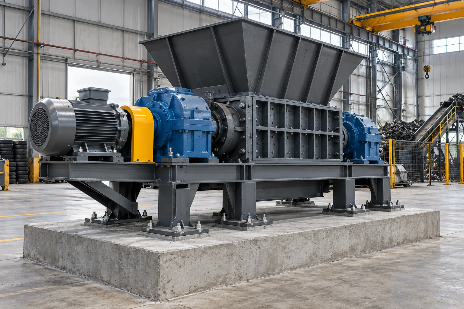
Three outlines belong on the layout. First is the installed footprint: the space occupied when the machine is ready to operate. Second is the civil footprint: foundations, anchor groups, pits, embedded plates and construction joints. Third is the maintenance envelope: the much less tidy area swept by doors, lifted gearboxes, removed cutter assemblies, rigging and personnel. A plan that only shows the first outline is unfinished, even if it looks attractive in a proposal.
What the civil engineer actually needs from the supplier
Machine weight is a starting point, not an anchor design. A shipping document may give the weight of the chamber, one drive and a spare part as three separate packages. The structure will see a different arrangement once everything is installed. In addition, the support reactions need not be equal. A motor and reducer on one side can shift the center of gravity well away from the middle of the frame.
The handover should be a small, controlled package: a layout drawing plus a load schedule. Where the manufacturer has not yet finalized an item, the schedule should say preliminary and identify what is still open. A contractor should not have to guess whether a number is a shipping weight or an operating reaction.
| Required information | Why the site team needs it | What to question if it is missing |
|---|---|---|
| Final machine configuration and drawing revision | Confirms that the feet and drive arrangement match the ordered equipment | Is the screen/return module included in the same base? |
| Operating and installation masses | Separates permanent loads from temporary lifting and handling loads | Are motors, hydraulic power packs and hoppers counted? |
| Center of gravity and individual support reactions | Allows the support system to be checked at the real contact points | Are reactions given for each foot, or only as one total? |
| Relevant horizontal, vertical and overturning actions | Supports review of the anchorage and concrete under defined load cases | How were start, stop, upset and reversal conditions treated? |
| Foot coordinates, plate dimensions and hole geometry | Gives surveyors, fabricators and the concrete crew workable setting-out data | What is the datum, and are dimensions to hole centers? |
| Elevations and permitted installation tolerances | Controls grout depth, mating conveyor height and shaft alignment | Are these survey tolerances or machine-running tolerances? |
| Removal routes and lifting points | Prevents walls, platforms and cables from blocking maintenance | Does the drawing show parts outside the assembled machine? |
A low-speed tire shredder does not behave like a constant dead load. Rubber grips and releases, a reinforced section can create a short resistance peak, and the control system may stop or reverse the shafts. None of that allows an engineer to invent a universal dynamic factor. The machine supplier must describe the applicable operating and exceptional actions, including the assumptions behind them; the project engineer determines the governing design cases under the relevant code.
Motor rating is another tempting shortcut. Two machines with similar installed kilowatts can have different reducers, cutter geometry, frame stiffness, mounts and reactions. Power is not a substitute for a support-load schedule. Nor can total mass be divided by the number of bolts to obtain an anchor tension. An anchor group resists a combination of actions through its geometry and connection details.
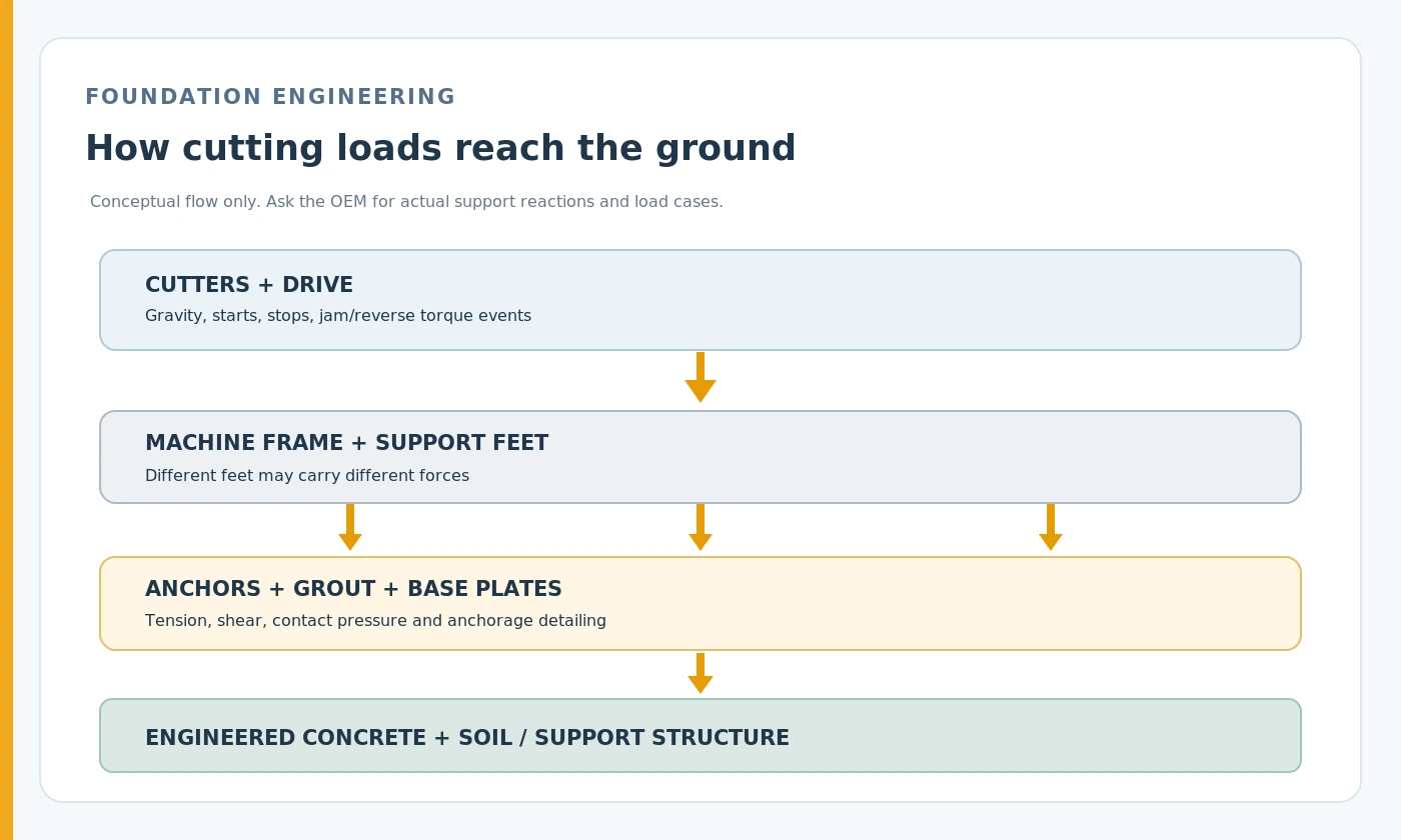
One detail worth chasing early is the origin of the load values. Do they refer to a bare machine at the factory, the machine on its permanent steel frame, or a complete module with conveyor supports attached? The answer changes who must design the connecting steel, and it may change the reactions sent to the concrete engineer. Put that definition in the notes, not only in a meeting minute.
Existing floor, new pad or independent foundation?
The right answer depends as much on the building as on the shredder. A workshop floor can look massive from above while containing a relatively thin slab, poorly documented reinforcement or services embedded near the proposed anchors. An older foundation block may have been designed for a different machine with loads in different locations. Simply choosing the option that avoids demolition is not a design method.
In a new building, the civil designer has room to coordinate slab thickness, reinforcement, anchor zones, construction joints and equipment elevation. In an existing building, much of the effort is investigation. The team may need original structural records, a condition survey, concrete testing and reinforcement or buried-service detection, as appropriate to the proposed modification. A suspended floor also introduces supporting beams and columns into the load path. Ground-bearing concrete is a different problem and still needs its subgrade and settlement conditions checked.
Do not assume that a raised concrete block automatically solves vibration. More concrete adds mass, but that alone says little about the behavior of the complete machine–foundation–soil system. Stiffness, connection details, excitation, damping and soil response matter. Likewise, isolating a foundation with a joint may help in one design and cause difficulties at transfer chutes, utilities and safety access in another. Those decisions belong to the project engineers using the supplier’s actual machine data.
There is also a practical floor-level question. A raised plinth might improve discharge clearance and protect the feet from washdown, yet make access to a low guard awkward or lift a gearbox closer to a crane obstruction. A recessed support can simplify one conveyor elevation and create a pit that traps debris and water. Before agreeing to either detail, walk through installation and service tasks with the elevations shown.
A useful decision record names the proposed support type, why it was selected, what site evidence was checked, who owns the anchor design and which drawing is released for construction. It need not be long. It does need to exist.
Anchor bolts are not a field adjustment mechanism
It is easy to talk about anchor bolts as if they were just fasteners holding the feet down. In reality, the anchor group, baseplate, grout and concrete form one engineered connection. Its behavior depends on load direction, bolt position, spacing, edge distances, embedment, concrete condition and the details of the plate itself.
Consider cast-in anchors first. They require accurate templates and careful checking before concrete placement. A small location error can be expensive because the bolt is already part of the structure. The template should use the same datum and hole-center convention as the machine drawing. Check that the template remains in position during the pour; checking it only the day before is not enough.
Post-installed mechanical or bonded anchors offer more flexibility on an existing floor, but only when the selected system is suitable for that concrete, the design actions and the installation conditions. Hole diameter, cleaning, moisture condition, temperature, embedment, curing and approved installation procedure cannot be improvised. Reinforcing steel conflicts must be resolved through the designer; a crew should not cut a bar to make a hole or shift an anchor to a convenient spot. Qualification, inspection and installer requirements vary by anchor system and jurisdiction.
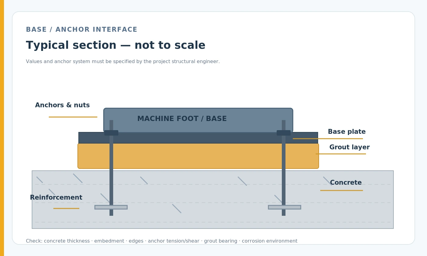
The site drawings should distinguish four things that often get mixed together: bolt size, anchor design, bolt installation procedure and final tightening method. The structural engineer may size the anchor group; the manufacturer may specify the machine foot and the tightening or pretension procedure; the anchor supplier provides the evaluated installation instructions. These documents must agree. If they do not, stop and resolve the conflict before drilling or pouring.
Do not assume a larger bolt is always better. It may require a larger hole or edge distance than the available concrete can provide. An anchor located too near an edge can be governed by concrete failure rather than bolt strength. Increasing the steel diameter does not automatically solve that problem. Similarly, welding a foot plate to an embedded item because the holes do not line up changes the connection unless the design explicitly permits it.
For the site acceptance file, a photo of a finished nut is of limited use. Keep the approved anchor layout, the product or material identification, required installation checks, recorded deviations and release signatures. If there was an approved repair, file the repair drawing alongside the as-built survey.
Grout, leveling and contact under the feet
When the machine is lowered into place, the frame has to sit at the intended height and orientation. Leveling screws or temporary shims may help the installers achieve that position, but the final load path must match the approved base detail. A thick, irregular grout patch used to compensate for a badly surveyed foundation is not a harmless cosmetic fix.
Start with the concrete surface. Check elevation, soundness, cleanliness and any surface preparation required by the grout design. Check the specified grout material, working time, placement method, curing and permitted loading period. Equipment grouts are not interchangeable merely because two bags carry the word ‘non-shrink’. Selection needs to suit the geometry and service conditions, with the manufacturer and designer approving the material and method.
The actual leveling procedure should come from the machine installation instructions. Some frames must be checked at defined reference points rather than at the nearest convenient top edge. After grouting, the crew needs an approved sequence for removing or retaining temporary supports, tightening anchors, checking alignment and releasing the foundation for operation. If the procedure calls for a later verification after initial service, that becomes a maintenance record rather than a guess from the installer.
An easy mistake is to level the shredder on its frame and forget the equipment attached to it. The discharge interface may have moved up with the grout. A rigid chute can then pull on a support it was never intended to load. Survey the interfaces before finalizing nearby steelwork. Corrections are much cheaper while conveyor brackets and guards are still adjustable.
Service clearance: follow the part that must come out
A walkway beside a running machine does not prove that the machine can be serviced there. The difference shows up on the day a reducer, coupling, screen assembly or shaft component must be removed. A worker might have room to reach the inspection cover but no straight path to pull the part away. The apparent solution—moving a conveyor or cutting a platform—can be a far larger job than the repair itself.
Review clearance by actual work sequence. Take the largest likely component, confirm how it is disconnected, where it travels after separation and which lifting device supports it. The route must be clear not only when the machine is assembled, but during every stage of the lift. A roof beam or cable tray can obstruct a hoist even where the floor plan looks open. Guards and removable panels matter too; their opened and removed positions should be shown rather than assumed.
A designer should trace at least these paths:
- Drive-side withdrawal. A gearbox or coupling may need axial movement before it can be turned or lifted. Check the shaft direction, flange separation and obstruction behind the drive.
- Top access. A major assembly may need vertical travel, slinging space, hook height and a clear route to the workshop floor. The crane’s rated capacity at the actual hook position must be checked separately.
- Cutter access. The door, cover or housing can open while leaving no working room for tools, staging and controlled movement of heavy parts. Details of cutter service belong in the separate shredder blade guide; here the question is whether the building permits that work to happen.
- Removal to a safe laydown area. A lifted part still has to pass people, railings, conveyors and storage. Designate where it can be set down and how it gets out of the workshop for repair.
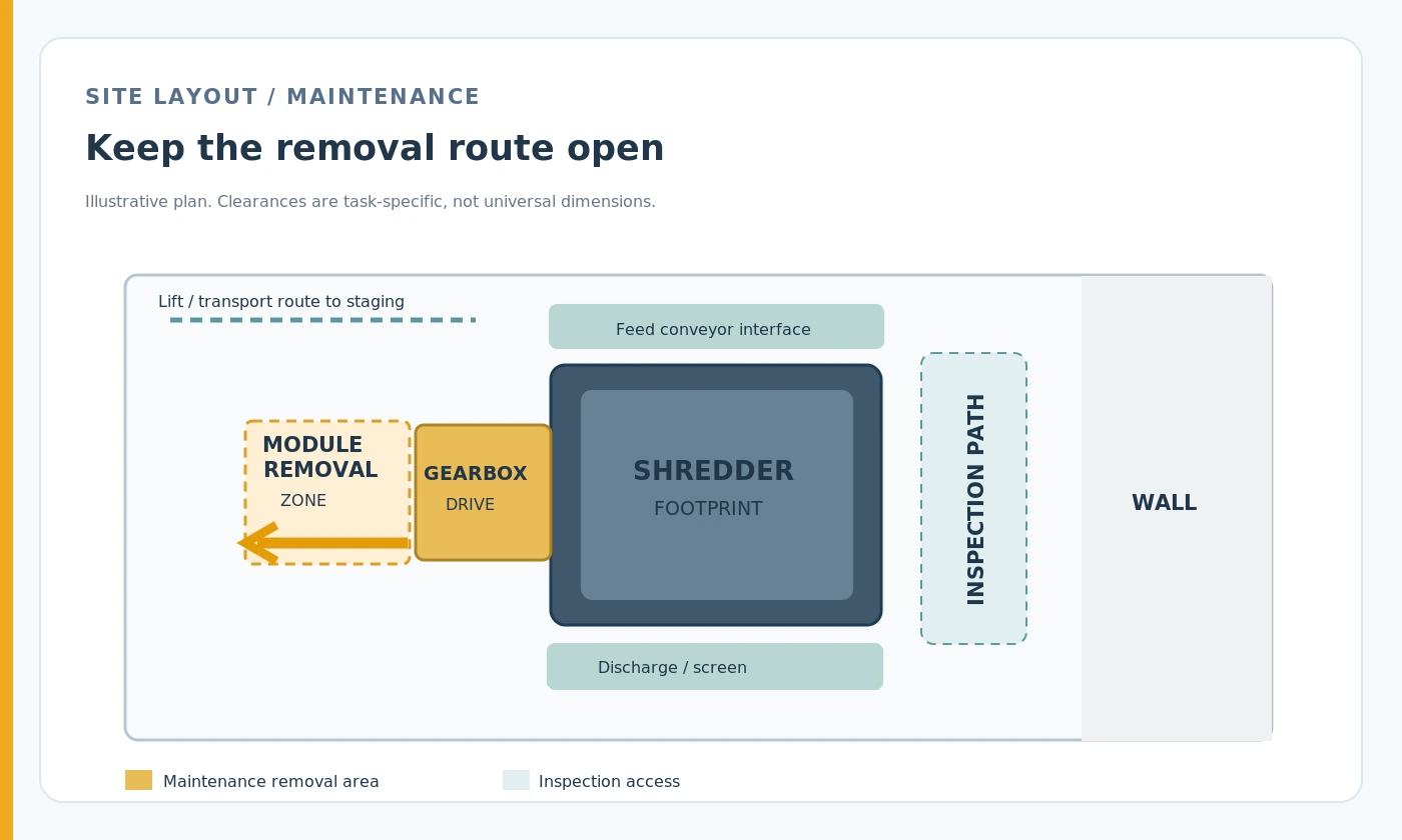
Do not confuse lifting headroom with ceiling height. Hook blocks, slings and lifting beams consume vertical space. A bridge crane cannot necessarily bring its hook directly beside a wall or column, and its capacity may depend on the operating position. Where no overhead crane is fitted, the rigging plan must establish whether a portable gantry, forklift or other approved lifting arrangement can reach the part. Forklift tines are not a generic substitute for engineered lifting points.
There is another trap in modular plants. A contractor may put a stair, electrical cabinet or return conveyor in the only free space beside the machine. Each item is individually reasonable; together they block the removal route. The layout review should therefore include the final surrounding equipment, not a clean drawing with only the shredder visible.
A simple clearance calculation—and why the result is not a standard
Suppose a hypothetical gearbox needs 1,450 mm of straight withdrawal according to its maker’s drawing. The approved lifting arrangement needs another 350 mm of working travel before the component can be turned, and the rigging plan reserves 300 mm for the next controlled movement. That produces a 2,100 mm illustrative working envelope for this particular task. It does not mean all tire shredders require 2.1 m at the drive side. Another model may use a different mounting system, come apart in smaller pieces or need substantially more room.
The point of the calculation is the method: define the removal sequence, read the real component dimensions, add the clearance genuinely needed by the tooling, and mark the resulting exclusion zone on the GA drawing. If the only available space falls short, change the layout or agree on a documented service method before construction. Do not assume the future maintenance crew will somehow manage.
The shredder does not sit alone
The foundation can be correctly built and still be compromised by the equipment installed around it. Feed conveyors, transfer chutes, oversize-return systems, guards, inspection platforms, electrical conduits and dust-control ducting all meet the shredder at specific positions. Every hard connection deserves a look.
Imagine a chute whose mounting holes sit slightly low. The installer may pull it into place with bolts. The chute then applies an unintended force to the machine support or nearby conveyor, and what began as an elevation error is hidden inside the finished assembly. The better approach is to check elevations and fit-up before final tightening. Where the approved design calls for a flexible connection, leave it flexible; welding it solid changes the arrangement.
The adjoining structure needs its own design logic. A feed conveyor support should not silently become a brace for the shredder because it happens to be close. An access platform should carry its intended live loads without leaning on guards or unsupported machine panels. Cable trays and pipes need movement or disconnection provision where equipment is expected to come out.
For an entire plant, the surrounding aisles and storage areas are discussed in the 3T/H line space guide. Here the concern is narrower: a single machine bay that can actually be installed, connected and maintained after the surrounding equipment is added.
Do not bury the electrical isolation points or access to anchor inspection under the screening return route. Leave enough light to see the underside of the frame. These sound like small housekeeping details during design; once the line starts running, they determine whether defects are found early or ignored because nobody can reach them.
A drawing review that prevents a gearbox-access mistake
Consider an illustrative retrofit. The plant has a clear space against the north wall and wants to place the shredder there to keep the feed conveyor short. The drawing leaves 900 mm between the gearbox end and the wall. On the preliminary plan, that appears to leave a walking gap when the machine is stopped; it does not establish safe access or service clearance. The project moves ahead until the installation contractor asks for the reducer’s removal drawing.
It turns out the unit cannot be lifted immediately upward. First it must move axially away from the shaft while supported by the approved rigging or temporary support arrangement. Only then can it follow the lifting and removal path. The available 900 mm is not the service distance, and a structural column blocks the crane hook position. Nobody did anything unusual during the civil design; the wrong dimension was simply being used as proof of adequate access.
There are possible corrections. Rotate the machine if the conveyor geometry permits it. Move the support pad before pouring. Keep a section of adjacent platform removable if that is an engineered, safe maintenance strategy. Or work with the supplier on an alternative approved service sequence. Each option has a cost, but the cost is visible while the drawings are still open. Discovering the problem after energizing the plant can turn a routine reducer change into a civil modification.
The lesson is not “always leave more room.” Unused floor area also costs money. Reserve space for named tasks, with dimensions that can be traced to the equipment and rigging plan. If the manufacturer changes a gearbox or motor arrangement after the layout is approved, the service envelope deserves another review even if the foundation-foot positions stay the same.
Freeze the right information before anyone pours concrete
The biggest handover failure is often version control. A general-arrangement PDF may circulate with an early motor position. A later revision moves the drive but retains the same overall machine width. The concrete subcontractor prints the first drawing and starts setting anchor templates. Everyone believes they have the latest information because the job title on the PDF matches.
A short release process helps. Give the civil team one approved drawing register containing the model or equipment serial reference, layout revision, foundation and anchor drawings, load schedule, and an explicit list of open issues. Mark preliminary files so they cannot be mistaken for construction releases. When the mechanical vendor changes a frame or support condition, identify the affected drawings and obtain the engineering approvals again.
Before concrete placement, hold a joint check at the machine location. It should include the civil contractor, equipment installer and the person responsible for the survey. Confirm not merely the coordinates on paper, but the physical conditions around them: embedded pipes, reinforcement conflicts, construction joints, finished-floor level, drains, pits and reach for anchor installation equipment. A foundation detail that works only when no other trade is present is not ready for construction.
| Project hold point | Evidence to keep | Who needs to agree before release |
|---|---|---|
| Layout and load package accepted | Controlled GA, load schedule, design responsibilities | Equipment supplier and responsible engineer |
| Existing structure checked or new support designed | Site investigation and approved civil design | Site structural/geotechnical engineers as applicable |
| Anchor locations ready for construction | Survey datum, template or drilling plan, conflict review | Civil contractor, installer and engineer |
| Concrete ready to receive the machine | Inspection records, relevant test results, elevation/as-built survey | Civil quality lead and installation lead |
| Machine supported and aligned | Level records, installed anchor documentation, approved grout release | Installer and responsible technical representatives |
| First controlled test authorized | Guarding, isolation, mechanical/electrical checks, outstanding-item list | Plant representative and commissioning lead |
This table is a handover aid, not a substitute for the contract’s inspection and test plan. Local rules may require other sign-offs, testing or inspections. The valuable part is that one accountable person can say when the machine is allowed to move to the next stage.
From truck arrival to first rotation
Installation work should not begin by tightening the first bolt that looks accessible. Start by identifying the crates and loose components against the packing list. Note transit damage and check that any temporary transport braces or shaft-locking arrangements are treated exactly as the supplier instructs. Lifting should use approved points and a documented plan for the actual mass, center of gravity and travel path.
Next comes the survey. Confirm the real support locations, elevations and anchor positions, not just the top of the concrete. Check the machine feet before lifting the frame onto them. This is the last cheap chance to identify an anchor conflict without a heavy machine standing in the way.
Positioning and leveling follow the approved instructions. Keep a record of the reference points used, because later alignment checks should be comparable. Install or complete the anchors according to their specified procedure. Place and cure grout as approved; do not treat its initial surface hardness as permission to apply operating loads. Bring adjoining conveyors and transfer points into alignment after the shredder’s support position has been established.
Electrical connections, guards and controls then need their separate commissioning checks. Verify protective devices, emergency-stop functions and the expected stop/reverse behavior under the supplier’s procedure. Exposed moving parts, stored hydraulic or mechanical energy, and unexpected startup are serious hazards. For servicing and maintenance, follow the facility’s hazardous-energy control program and the applicable regulations, including OSHA’s lockout/tagout rule where relevant in the United States.
Avoid using a fully loaded shredder as the first test of the entire installation. The commissioning plan should define the permissible sequence and the data to collect, beginning with approved pre-start checks and no-load operation where specified. During initial running, observe the feet, joints, grout and adjacent connections from safe positions. Look for movement, cracking, changes in alignment, unusual sound and evidence of loosening. An observation deserves investigation before someone attempts to make the symptom disappear by tightening or shimming a random point.
Repeated reversals or high motor current may originate in the cutting process rather than the foundation. The separate shredder troubleshooting guide covers those machine symptoms. On this page, the commissioning question is whether the support system and installed interfaces remain sound while the machine experiences its approved operating conditions.
What should be left in the site file?
A finished foundation is hidden by the machine, guard panels and conveyors. After handover, the drawings and measured records may be the only easy way to understand what is underneath. Keep the as-built foundation and anchor locations, approved deviations, grout records, installation survey, relevant inspection reports, lifting/removal plan and the final equipment layout. Store them under the machine identifier, not only under the original construction contract.
It is worth taking labeled photographs before the last grouting or cover-up steps. Photograph anchor groups and interfaces with references that let someone identify their position later. A folder of unlabeled close-ups is less useful than two clear views linked to a drawing. Where measurement records exist, include the date, instrument or method, the acceptance criterion and the person who signed off.
The operator also needs a baseline for future inspection. The plant’s routine inspection program may include visible fasteners, support distress, leaks, vibration or changes after major maintenance; the separate maintenance checklist addresses recurring tasks. There is no benefit in copying that whole schedule here. What matters at installation handover is that the original condition has been documented, so future changes can be recognized rather than debated from memory.
Keep major service access zones free of permanent storage. A bay that was clear on acceptance day can become a parking place for spare motors, crates and discarded steel. Marking removal and lifting zones on the approved shop plan makes them easier to protect during later layout changes. If production proposes a new platform, electrical cabinet or partition, check it against those service zones first.
Questions to settle before the purchase order becomes a concrete pour
The procurement team does not need to design the foundation. It does need to make sure the purchase documents require information that the civil team can use. A brochure with overall dimensions is rarely enough to tender a machine bay accurately.
In the supplier’s technical discussion, cover the following points in plain language:
- Exactly what is being supported? Confirm whether the supplied frame, drives, screen and return system are one assembly or separate installed modules.
- Which drawing is for construction? Request revisions, dates and equipment identifiers rather than an unlabeled sketch.
- What loads go where? Obtain support coordinates, reactions and identified operating or exceptional load cases. Ask how any missing values will be resolved.
- Who designs the anchors? Allocate responsibility for the anchor group, concrete, base plates, installation method and inspection. Agree how deviations are handled.
- How will heavy parts come out? Request weights, lift points, withdrawal distances and the order in which guards or neighboring items must be removed.
- What site constraints are known now? Send drawings showing walls, columns, finished floor, embedded services, drains, lifting equipment, nearby machines and limits on demolition.
- What happens if the supplied machine changes? Make the vendor’s change-notification and drawing reapproval process explicit.
If the supplier cannot yet issue a final support reaction schedule, the project can still discuss layout options. It should not silently convert preliminary dimensions into a permanent foundation design. A clear “not released for construction” note is less expensive than an undocumented assumption.
Tire Shredder Foundation & Installation FAQ
Can a heavy-duty tire shredder sit on an ordinary workshop slab?
Possibly, but appearances and machine mass do not answer the question. The engineer must establish what the slab is, how it is supported, what condition it is in, and whether it can resist the manufacturer’s actual support and operating actions. A suspended floor and a slab on grade require different checks. Where records are incomplete, site investigation may be needed.
Is there a recommended concrete thickness for every tire shredder?
No. A thickness quoted without soil, reinforcement, geometry, loads, anchors and local design criteria is not a reliable specification. Use the machine interface data and an approved structural design. A thicker pad is not automatically a better foundation.
Are chemical anchors an acceptable substitute for cast-in bolts?
They can be appropriate in some designs, particularly retrofits, but only where the selected bonded-anchor system and its evaluated installation conditions are suitable. Concrete condition, loads, edge distances, embedment, hole cleaning, curing and inspection all matter. The engineer must approve the substitution before the crew drills.
How much room is needed next to the gearbox?
There is no single clearance that works for every reducer arrangement. Start with the manufacturer’s withdrawal or removal drawing, then check rigging space, hook reach, safe access and the path to a laydown area. A normal walking aisle may not be enough to remove the drive.
Who should decide where the anchor bolts go?
The approved equipment foot pattern establishes the machine interface. The structural or anchorage designer checks the bolts and concrete for the required actions, while the installer follows the coordinated construction drawings. Any conflict between hole locations and reinforcement, conduits or edges needs an engineered resolution—not an on-site guess.
What is the last check before releasing the shredder to production?
Confirm that the support, anchors, leveling, grout and interface connections have been inspected and accepted; that guarding, isolation and lifting/access arrangements are in place; and that the commissioning sequence has been authorized. Any movement, distress or abnormal connection behavior during the controlled tests must be investigated before routine loading.
Request installation information for your machine bay
A tire shredder quotation is more useful when the civil engineer can build from the same machine layout the equipment supplier intends to deliver. Send YUXI the tire feed type, proposed equipment arrangement, workshop plan, foundation or existing-slab drawings if available, and details of cranes, columns, platforms and conveyors. Request the model-specific GA drawing, support information and removal envelope needed to develop the site design. The final foundation and anchor design remains with the appropriately qualified project engineer.
Reference notes
This article is intended for early engineering coordination. It is not a certified foundation detail, anchor calculation or installation procedure. A project in the United States may need to consider applicable provisions of ACI 318 for anchorage and concrete design, relevant guidance such as ACI 351.3R on foundations for dynamic equipment, the adopted building code, and applicable safety regulations. Requirements differ by jurisdiction and project. The approved manufacturer drawings and licensed local design govern the work.