




The rubber looked right at the discharge conveyor. Most pieces were roughly thumbnail-sized, and the operator could not see an obvious oversize problem. Yet the customer’s sieve check failed the load: too much material below 10 mm, a small but unacceptable fraction above 20 mm, and no record of how the sample had been taken.
This is the difficult part of making 10–20 mm rubber mulch. The headline range sounds like one machine setting. It is actually a line-control problem involving feed preparation, rasper cutting, screen geometry, material depth, oversize recirculation, fines handling and a repeatable acceptance test. When one of those parts is left undefined, the product can look uniform and still be commercially inconsistent.
What Controls 10–20 mm Rubber Mulch Size?
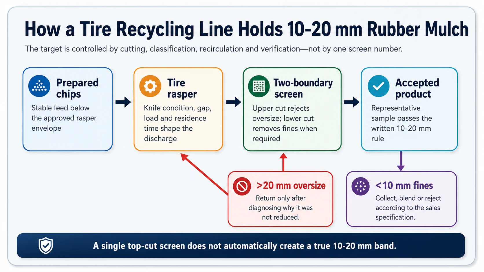
Producing consistent 10–20 mm rubber mulch depends on more than selecting a 20 mm screen. The final size distribution is affected by rasper cutting conditions, screen aperture and shape, feed consistency, recirculation load, blade wear, and the way finished material is sampled. A single upper-deck screen can control oversize particles, but a true 10–20 mm specification normally requires both upper- and lower-size limits to be verified.
Record the oversize return mass, because recirculation consumes rasper and conveyor capacity. Verify the final product with a composite sample taken across a representative run. Capacity should be reported as accepted finished tons per hour after the agreed size, steel and textile checks—not as gross rasper discharge.
On This Page
- Define the 10–20 mm product
- Six size-control points
- Control the rasper discharge
- Select and operate the screen
- Use two cuts for a true range
- Control oversize recirculation
- Measure particle-size distribution
- Protect accepted capacity
- Troubleshoot size drift
- Factory acceptance test
- RFQ information
- Frequently asked questions
Start by Defining What “10–20 mm” Means
A range printed in a brochure is not yet a product specification. It can mean at least four different things:
Nominal machine output
Most pieces appear to fall near the target during a normal run. This is useful for product orientation, but it is too vague for acceptance.
Top-cut product
Material must pass an agreed upper screen, while fines below the stated range may remain in the product.
Band-pass product
Material must pass the upper cut and remain above a lower cut, subject to written tolerance for oversize and undersize.
Maximum-piece rule
The buyer limits the longest dimension of any chip. This is not automatically the same as passing a sieve aperture.
Before selecting equipment, write the rule in measurable terms. A practical purchase specification should state the upper cut, lower cut if required, allowed percentage outside the range, maximum individual piece, test sample mass, sampling location, test duration and whether results are reported by mass.
Important distinction: “10–20 mm” should not be interpreted as every chip measuring between exactly 10.0 and 20.0 mm in every direction. Tire-derived rubber is irregular. The commercial question is the allowed distribution and the agreed method used to measure it.
The Six Control Points That Determine Rubber Mulch Size
| Control point | What it changes | What to record |
|---|---|---|
| Incoming chip condition | Large, folded or highly variable pieces create unstable cutting and uneven residence time. | Feed source, tire mix, approximate maximum chip, long strips and foreign material. |
| Rasper knife condition and gap | Dull, damaged or poorly set cutting elements can raise oversize, heat and irregular tearing. | Service hours, inspection result, knife rotation or replacement, approved gap setting. |
| Feed rate and rotor load | Surges can push material through the cutting chamber before the intended reduction is achieved. | Feeder setting, motor-load trend, overload events and bridge clearing. |
| Screen geometry and condition | Opening shape, effective open area, wear and blinding determine what can pass. | Aperture drawing, thickness, open area, wear, blockage and installation date. |
| Oversize return loop | Recirculation stabilizes top size but consumes machine capacity and can create excess fines. | Return mass or belt trend, number of passes if traceable and reason for abnormal return. |
| Sampling and sieve test | A poor sample can make a stable process look unstable—or hide a real problem. | Sample points, increments, composite method, sieve stack, time, mass and result. |
These controls interact. Tightening the screen without checking knife condition may increase return load rather than improve the rasper’s first-pass cut. Raising feed rate to recover tonnage may deepen the burden on the screen and allow more misclassification. Good control comes from changing one verified variable at a time and preserving the mass balance.
Control the Rasper Before Asking the Screen to Fix the Product
A screen classifies material; it does not replace effective secondary cutting. The tire rasper machine guide explains the rotor, knives, screen and steel-liberation role in more detail. For size control, four operating conditions matter most.
1. Keep the incoming chips inside the approved feed envelope
YUXI’s mulch configuration normally places the rasper after primary shredding, with prepared chips below approximately 100 mm used as the reference feed condition. “Below 100 mm” should not be read as permission for an uncontrolled mix of compact blocks, long strips and folded pieces. Shape and consistency still affect metering and cutting.
We normally recommend photographing and weighing a representative feed sample during the factory trial. If the customer will operate with a different tire mix or a different upstream shredder, that difference should be stated before the trial result is treated as a production guarantee.
2. Maintain the cutting edge and approved knife relationship
A worn edge can continue to move material while producing a broader discharge. The operator may first notice a higher return rate, more heat, a rougher chip surface or longer residence time rather than a sudden stop. That is why output gradation should be trended alongside knife inspection instead of waiting for a visible mechanical failure.
3. Feed steadily enough to avoid starvation and surging
A starved rasper wastes installed capacity. An overfed rasper can create a thick, unstable chamber load and raise the fraction that leaves too coarse. A controlled feeder, level signal or current-based interlock can help, but the commissioning team still needs to find the stable operating window with the actual chip mix.
4. Separate size reduction from steel recovery measurements
The rasper cuts rubber and liberates embedded steel. A downstream magnet recovers the released ferrous fraction. An oversize chip may still contain steel because it has not been cut sufficiently, while a correctly sized chip may carry loose wire if the magnetic burden is too deep. Particle size, steel liberation and final visible steel are related, but they are not one measurement.
Choose the Product Screen by Trial, Not by a Universal Hole Number
It is tempting to say that a 20 mm opening makes a 20 mm top size. That shortcut is unreliable for irregular rubber. A long, narrow chip may pass through an opening when aligned. A flexible chip can deform. A rounded opening, slotted opening and square opening with the same nominal width do not classify the same way. Plate thickness and the ratio of open area to solid area also change passage.
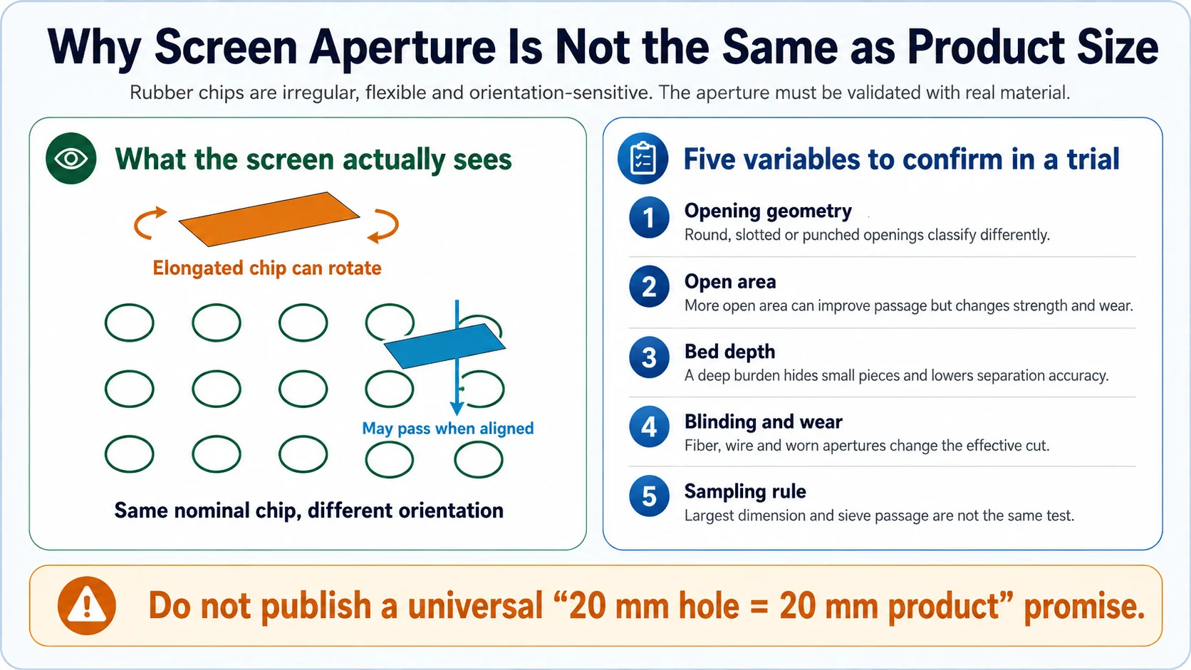
Screen variables that should appear in the equipment file
- Opening shape and dimensions: include a drawing rather than only a nominal size.
- Plate or mesh thickness: thick openings can behave like short channels and change passage.
- Effective open area: lower open area can restrict throughput and increase bed depth.
- Screen motion: vibration amplitude, frequency, inclination or trommel speed must suit the configured classifier.
- Feed distribution: material should spread across the usable width instead of forming one deep lane.
- Blinding control: textile, loose wire and irregular chips can block openings and shift the effective cut.
- Wear allowance: worn openings can enlarge, deform or crack, producing gradual quality drift.
On one export project, the useful commissioning question was not “Which screen did you install?” It was “What fraction passed each test sieve after two hours of representative running, and what was the return load while that sample was produced?” That question connects hardware to the accepted product.
A True 10–20 mm Band Requires Two Size Cuts
The upper boundary and lower boundary perform different jobs.
Upper cut: control oversize
Material larger than the accepted top cut returns to the rasper or another approved reduction stage. This protects the maximum product size.
Lower cut: control undersize
Material below the accepted lower cut is removed as fines, collected as a separate product or blended only when the buyer allows it.
A single screen placed after the rasper often operates as a top-cut classifier. It can make a product described as “nominal 10–20 mm” when the rasper naturally produces limited fines and the market accepts that distribution. However, it cannot prove that all material below 10 mm has been removed.
When the customer needs a stricter band-pass product, use a two-deck screen, two sequential screens or another validated classification arrangement. The exact screen sequence depends on equipment design, but the commercial logic is constant: separate oversize, accepted product and undersize as three measurable streams.
Specification language that helps: “Report mass percentage retained above the upper test sieve, mass percentage passing the lower test sieve, and mass percentage within the accepted band.” This is much clearer than asking for “uniform 10–20 mm chips.”
Control Oversize Return Before It Becomes an Invisible Bottleneck
Returning oversize is useful. It gives the large pieces another controlled pass instead of sending them to the finished conveyor. The problem begins when the return loop becomes so large that the rasper spends much of its time reprocessing its own discharge.
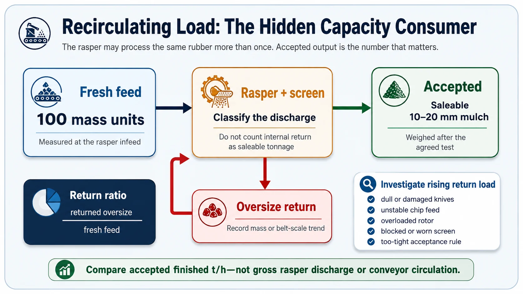
Return ratio = mass of oversize returned during the test ÷ mass of fresh feed during the same test
The return ratio is not a universal pass/fail number. It is a diagnostic trend. A stable tested configuration may run with a normal recirculating load. A rising ratio at the same feed and screen condition suggests that something has changed.
Investigate return-load increases in this order
- Confirm that the incoming chip size and tire mix have not changed.
- Inspect rasper knives, approved gap and chamber wear under the required safe-state procedure.
- Check for feeder surging, rotor overload or repeated current peaks.
- Inspect screen blinding, damage, incorrect installation and uneven material distribution.
- Review whether the operator tightened the product rule or changed the sieve interpretation.
Repeated passes can also create more fines. That is why “keep returning everything until it passes” is not a complete control strategy. The line needs a practical first-pass cut and a return loop sized for the tested normal load, not for permanent correction of an upstream cutting problem.
Measure the Distribution With a Representative Composite Sample
ASTM D5644 describes a mechanical vibratory sieve method for determining the particle-size distribution of recycled vulcanized particulate rubber at 90 μm and larger.1 ASTM D5603 classifies recycled vulcanized particulate rubber using particle-size distribution and origin information.2 These standards support the basic discipline of sieve-based reporting, although a 10–20 mm irregular mulch contract still needs to state the exact sieves, sample mass and any project-specific handling rules.
A practical production sampling sequence
- Select the point: sample the accepted-product conveyor after the configured size-control and separation stages.
- Take increments across time: collect small portions at regular intervals rather than one convenient scoop.
- Build a composite: combine the increments, mix them and reduce the sample without hand-picking attractive pieces.
- Record wet or dry condition: surface moisture and adhered fiber can affect handling and apparent mass.
- Sieve for a fixed time: use the agreed equipment and avoid changing shaking time between suppliers.
- Weigh each fraction: report retained and passing percentages by mass, including pan fines where applicable.
- Inspect maximum pieces: perform a separate longest-dimension check if the contract requires one.
The U.S. EPA notes that tire-rubber processing uses screens for size classification and return of oversize, magnets for metal removal and air systems for fabric separation; it also points to ASTM D5644 for particle-size distribution.3 That is a useful process model. It should not be converted into a claim that one standard test automatically proves playground suitability, chemical safety or every other end-use requirement.
For a complete configured route from tire chips to wire-free mulch, see YUXI’s Tire Wire Free Mulch Plant.
Measure Capacity at the Accepted-Product Conveyor
Accepted finished capacity = mass of product passing the agreed size and quality checks ÷ measured net production time
This definition prevents three common quotation errors:
- Counting fresh feed that later becomes oversize return.
- Counting broad rasper discharge before the product screen.
- Using a short peak run that excludes normal screen cleaning, knife checks or process stops.
A tighter size band usually increases cutting and classification work per accepted ton. It may require slower fresh feed, higher internal recirculation or a larger rasper and screen. The correct comparison is not “Which line has the highest nameplate t/h?” It is “Which line produces the required accepted distribution continuously from the representative tire mix, and what are the return load, wear condition and energy trend during that test?”
The 10–20 mm stage can be a finished mulch product or prepared feed for a later granulator. The rubber mulch vs crumb rubber comparison explains why continuing below mulch size adds granulation, tighter screening, secondary magnetic recovery and stronger fiber control. Do not reduce mulch size further unless the buyer and equipment scope justify the additional operating depth.
Troubleshooting Rubber Mulch Size Drift
| Observed problem | Likely checks | What not to assume |
|---|---|---|
| More pieces above 20 mm | Feed chip change, knife wear, gap, feeder surge, rotor load, screen blockage or damaged aperture. | Do not assume the screen alone is too large. |
| More material below 10 mm | Excessive recirculation, over-processing, broken screen, changed knife condition or new brittle feed behavior. | Do not assume fines can always be blended into saleable mulch. |
| Size varies by shift | Operator feed practice, tire mix, screen cleaning, knife-service timing and sampling inconsistency. | Do not compare samples taken from different locations or durations. |
| Return conveyor remains full | Confirm fresh feed rate, first-pass reduction, screen open area, blinding and return-conveyor capacity. | Do not raise conveyor speed before finding why oversize increased. |
| Product passes sieve but contains long chips | Opening geometry, orientation effect and maximum-piece rule. | Do not treat sieve passage and longest dimension as identical. |
| Product size is correct but steel complaints increase | Steel liberation, magnet burden depth, belt settings, tramp wire and sample inspection. | Do not use particle size as proof of wire-free quality. |
Safety boundary: Screen clearing, knife inspection, chamber access and blockage removal may expose hazardous mechanical and stored energy. Follow the supplied machine manual, guarding requirements and the site’s energy-control procedure. OSHA’s lockout/tagout rule covers servicing where unexpected energization or release of stored energy could cause injury.4
Factory Acceptance Test for 10–20 mm Rubber Mulch
A useful FAT should reproduce the commercial feed and collect enough data to explain the result. A polished sample bag produced before the customer arrives proves very little.
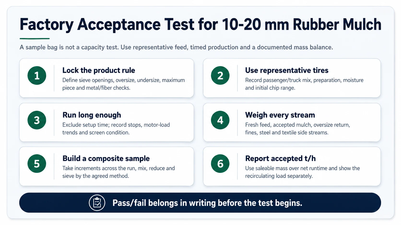
Minimum FAT record
- Representative tire categories and proportions.
- Preprocessing route and primary chip-size condition.
- Rasper knife condition and approved setup.
- Screen drawing, opening geometry and installed condition.
- Fresh-feed mass and measured net runtime.
- Accepted product mass.
- Oversize-return mass or calibrated trend.
- Undersize or fines mass where a lower cut is specified.
- Recovered steel and textile side-stream observations.
- Composite sample method and complete sieve results.
- Motor-load trend, stops, alarms and operator interventions.
- Photographs of the feed, screen, accepted product and out-of-range fractions.
The FAT should state whether the pass criterion applies to one sample, the average of several composite samples or every tested sample. It should also state what happens after a fail: adjust and retest, change the screen, change the feed envelope or revise the accepted capacity. Leaving that decision until after the run invites a commercial argument rather than an engineering correction.
What to Send YUXI for a 10–20 mm Size-Control Review
- Photos and video of the whole tires or existing primary chips.
- Tire mix: passenger, truck and any larger or unusual tires.
- Maximum chip dimensions, long-strip content and loose wire condition.
- Required product definition: nominal range, top cut or true band-pass.
- Allowed oversize and undersize percentages by mass.
- Maximum individual piece rule, if any.
- Visible steel and textile-fiber acceptance requirements.
- Target accepted-product t/h and planned operating hours.
- Whether 10–20 mm material will be sold directly or fed to crumb production.
- Preferred sampling method, customer test sieves and sample mass.
- Available floor space, power supply, dust handling and packing route.
With those inputs, the discussion can move beyond “Which screen makes 20 mm?” and toward the line configuration, classifier area, return capacity and acceptance evidence needed for the actual market.
FAQ
Does a 20 mm screen guarantee every rubber chip is below 20 mm?
No. Rubber chips are irregular and flexible, and elongated pieces can pass depending on orientation and opening geometry. The screen opening must be validated with representative material and a written sampling method.
Is one screen enough to make a true 10–20 mm product?
One upper-cut screen can reject oversize, but it does not automatically remove material below 10 mm. A true two-sided range usually requires a lower cut for undersize or fines, an upper cut for oversize, and an agreed distribution tolerance.
Why does the oversize return load keep increasing?
Common causes include dull or damaged rasper knives, unstable feed size, excessive feed rate, poor material distribution, screen blinding, aperture wear or an acceptance rule that is tighter than the tested configuration can sustain.
How should 10–20 mm rubber mulch capacity be measured?
Measure the mass of accepted product that passes the agreed size and quality checks, divided by the measured net production time. Report fresh feed, returned oversize, undersize, steel and textile side streams separately.
Can 10–20 mm rubber mulch be processed into crumb rubber later?
Yes, when the chip size, residual steel, textile content and feed consistency suit the downstream granulator. The mulch product specification should be agreed as a granulator feed specification rather than assumed from appearance.
Which standard can be used for particle-size testing?
ASTM D5644 provides a method for determining the particle-size distribution of recycled vulcanized particulate rubber. For coarse irregular mulch, the buyer and supplier should confirm how the standard or a project-specific sieve method will be applied.
External Engineering References
- ASTM D5644-23, Determination of Particle Size Distribution of Recycled Vulcanizate Particulate Rubber. Used for the principle of mechanical sieve-based particle-size distribution reporting.
- ASTM D5603-23, Classification for Recycled Vulcanizate Rubber. Used for classification context; not presented as a universal mulch product specification.
- U.S. EPA, Tire Crumb Questions and Answers. Used for the staged process model of screening, magnetic metal removal, fabric separation and particle-size testing.
- OSHA 29 CFR 1910.147, The Control of Hazardous Energy. Used only for the maintenance and servicing safety boundary.
Define the Size Test Before You Select the Screen
Send YUXI your representative tire chips, required 10–20 mm distribution, oversize and fines tolerances, accepted-product capacity and sampling method. The proposal can then size the rasper, screen and return loop around a measurable product rather than a nominal hole size.