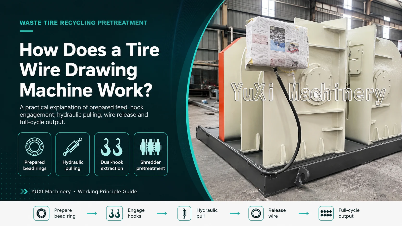
The machine does not draw new wire through dies. It uses hydraulic pulling force and high-strength hooks to extract the steel bead bundle from a prepared waste-tire ring.
YUXI tire wire drawing machine working principle: prepare, position, engage, pull, separate and reset.
A buyer watching a short working video can easily miss the most important part of the process: the pulling stroke is only one stage of a complete tire-debeading cycle. Feed preparation, stable positioning, hook engagement, output clearing and reset determine whether the machine works consistently in a real recycling plant.
YUXI describes its tire wire drawing machine as a hydraulic double-hook tire debeader for removing bead steel wire from prepared radial tire rings before tire cutting, shredding, rubber-powder production or related pretreatment. The public product information identifies rings with both sidewalls removed as the normal feed condition and says final model details should be confirmed around tire size, bead construction and project layout.
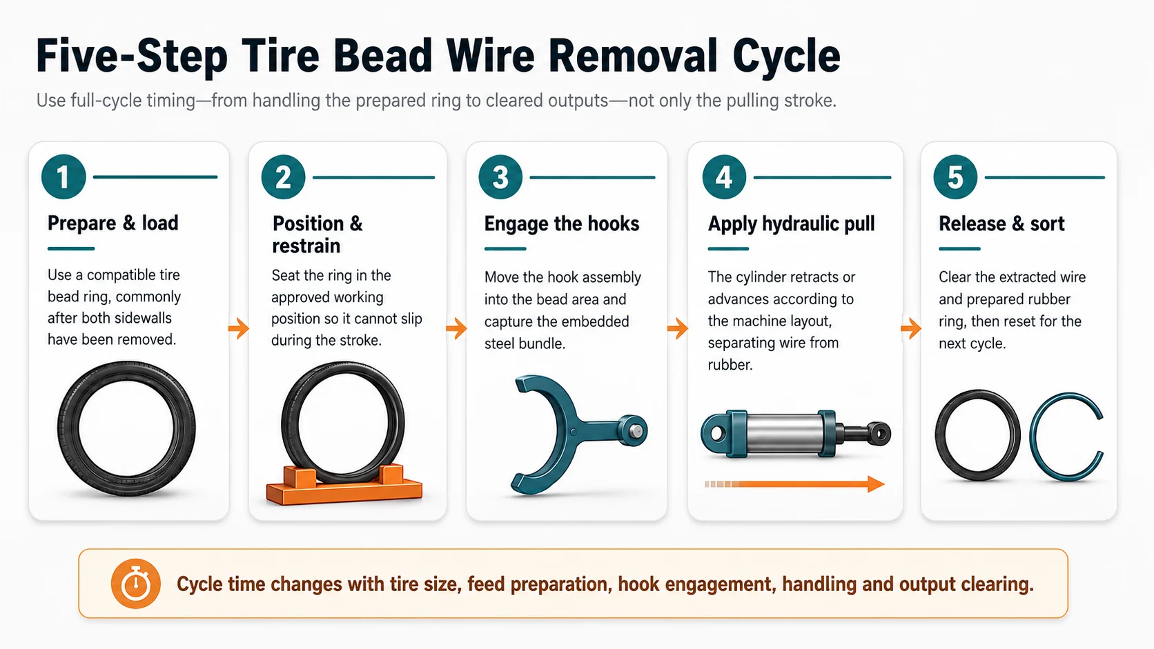
A tire wire drawing machine works by converting hydraulic pressure into a controlled linear pulling force. The operator loads a compatible prepared bead ring, the workpiece is positioned and restrained, one or more hooks engage the bead-wire bundle, and a hydraulic cylinder moves the hook assembly through the extraction stroke. The steel bundle separates from the surrounding rubber, the two outputs are cleared, and the mechanism resets for the next ring.
The operating sequence can be summarized as locate → engage → pull → separate → reset. The engineering challenge is not merely generating force. The machine must transfer that force through the cylinder, hook, tire ring and frame without uncontrolled workpiece movement or unsafe exposure at the point of operation.
1. What Actually Enters the Machine?
The phrase “tire wire drawing machine” sometimes creates the impression that an operator can place any whole tire into any machine and pull out all internal steel. That is not a safe purchasing assumption. Tires contain several steel-containing components, including bead bundles near the rim and steel belts beneath the tread. A debeader is intended to remove the concentrated bead-wire bundle, not to extract every steel cord from the complete casing.
The U.S. Tire Manufacturers Association explains that tire bead bundles are strands of wire that secure the tire to the wheel, while steel wire is also used in belts and, for truck tires, may be used in the plies. USTMA’s manufacturing description adds that strands of steel wire are formed into two hoops and embedded into the tire structure to create the bead.12
Verified YUXI feed boundary: the public YUXI product page describes prepared radial tire bead rings, especially rings with both sidewalls removed. It lists passenger-car, bus and truck tire material as possible applications depending on size and configuration. A buyer should confirm the exact incoming shape, minimum and maximum dimensions and whether any upstream cutting step is required.
This feed condition matters because preparation exposes or makes the bead region accessible, removes unnecessary flexible material from the working zone and creates a more repeatable ring for loading. It also explains why a tire bead cutter and a tire debeader are not interchangeable. The Tire Bead Cutter vs Tire Debeader guide covers that decision boundary in detail.
2. The Core Working Principle
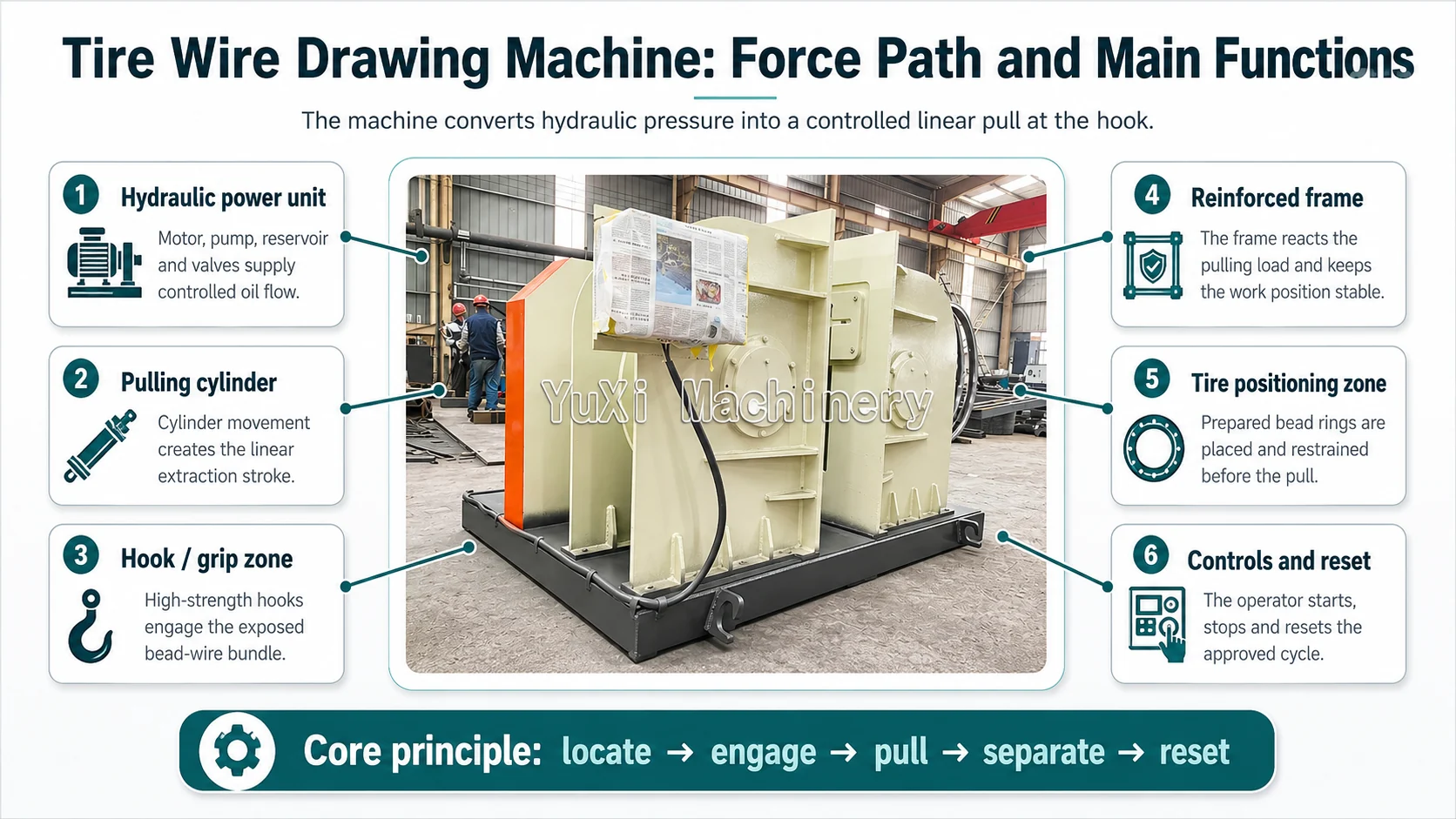
At the center of the machine is a simple mechanical relationship: a hydraulic cylinder creates a linear stroke; the hook assembly transfers that motion into the bead wire; the machine frame reacts the load; and the rubber deforms or tears locally as the bonded steel bundle is extracted.
This is different from a metalworking wire-drawing machine, which reduces wire diameter by pulling metal through dies. In waste-tire recycling, “wire drawing” is an industry name for pulling an existing bead bundle out of rubber. The machine is therefore also called a tire debeader, tire wire removal machine or tire bead wire remover.
The force path must be treated as one system. Pulling force is useful only when the hook engages correctly, the tire ring remains controlled and the frame reacts the load.
3. Step by Step: The Complete Operating Cycle
Prepare and load a compatible bead ring
The operator or upstream process presents a tire bead ring in the condition approved for the machine. For the YUXI product described publicly, this normally means a prepared radial tire ring rather than an unprocessed whole tire. Mixed tire types should not be treated as identical merely because their outside diameters look similar.
Position and restrain the workpiece
The ring is placed in the working position and held so it cannot travel with the hook. Stable presentation is essential: if the tire slips, twists or rises during the pulling stroke, the hook may lose engagement, the wire may break into an undesirable shape, or the cycle may need to be stopped.
Move the hook into the bead area
The hook or hooks enter the accessible bead zone and capture the high-tensile wire bundle. This is a geometry problem as much as a force problem. The hook profile, tire-ring preparation, approach path and bead construction determine whether the bundle is captured cleanly.
Apply the hydraulic pulling stroke
The hydraulic control directs oil to the cylinder. Cylinder movement drives the hook assembly through the extraction stroke. As tension rises, the wire bundle pulls against the surrounding vulcanized rubber. The rubber deforms and releases progressively until the bead bundle is drawn out.
Release, sort and reset
The extracted steel wire and the remaining rubber-rich ring are removed to separate collection points. The hook returns to the loading position and the cell is prepared for the next ring. This output-clearing and reset time belongs in the production cycle even though no wire is being pulled during those seconds.
For throughput planning, start timing when the next unprocessed ring is handled and stop when both outputs are cleared to their intended locations.
4. Main Components and What Each One Does
Component
Function in the working principle
What the buyer should verify
Hydraulic power unit
Supplies pressurized oil and controlled flow for the pulling and return movements.
Motor and voltage, reservoir arrangement, cooling if fitted, valves, filtration and documentation.
Hydraulic cylinder
Converts hydraulic energy into a linear pulling stroke.
Verified pulling capability, stroke, mounting, hose routing, seals and accessible service information.
Hook assembly
Engages the exposed bead-wire bundle and transfers cylinder force into the steel.
Single- or double-hook arrangement, hook material, wear surfaces, replacement method and spare-hook supply.
Tire positioning structure
Controls the prepared ring so the hook can pull without the workpiece following the stroke.
Acceptable ring dimensions, loading direction, restraints, handling clearance and test evidence using representative tires.
Machine frame
Reacts the pulling load and maintains alignment among the workpiece, hook and cylinder.
Machine footprint, anchoring requirements, access clearance and transport or installation information.
Controls and guarding
Start, stop and reset the approved cycle while separating the operator from hazardous movement.
Operating mode, emergency controls, guard arrangement, interlocks if fitted and machine-specific safe-use documentation.
5. How the Hydraulic Pull Creates Extraction Force
Hydraulic systems are used because they can create a high, controllable linear force in a compact mechanical arrangement. Conceptually, cylinder force is related to hydraulic pressure and piston area. That relationship is useful for understanding the machine, but it is not a field instruction to increase pressure.
Conceptual cylinder force = hydraulic pressure × effective piston area
Real extraction performance also depends on mechanical losses, cylinder direction, hook geometry, alignment, tire condition and how the bead bundle releases from rubber. A higher pressure reading does not automatically mean a cleaner or safer pull. Pressure limits, valve settings and adjustments are machine-specific and should remain within the supplied documentation and authorized service procedure.
During the stroke, the hook places the bead bundle in tension. The positioning structure and frame react the opposite load. If engagement is shallow, the ring is poorly prepared or the workpiece moves, the hook can slip before the available hydraulic force is productively transferred. This is why a credible working video should show the complete feed, engagement and output—not only the cylinder moving.
6. What Changes in a Double-Hook Tire Debeader?
YUXI publicly describes the machine as a hydraulic double-hook tire debeader. A double-hook configuration can be arranged to engage the two bead areas in one loading setup or reduce the need to reposition the ring, depending on the exact machine geometry and tire preparation.
Do not assume “double hook” means exactly twice the production capacity. Output still includes loading, alignment, hook engagement, the active pull, release, sorting, reset and any failed engagement or repositioning. Tire weight, bead strength and operator handling may dominate the cycle.
7. What Comes Out of the Machine?
A successful debeading cycle creates two distinguishable streams:
Extracted bead-wire bundle
The high-tensile steel bundle is pulled from the bead area. Its final shape and rubber contamination depend on tire construction, feed preparation and extraction quality. It should be handled and stored as sharp, spring-like scrap steel rather than as a harmless flexible cable.
Prepared rubber-rich tire ring
The remaining ring has substantially less concentrated bead steel and can be routed to the next approved size-reduction step. It may still contain belt steel and other reinforcement; debeading is not the same as producing completely wire-free rubber.
The EPA/USTMA scrap-tire handbook defines bead wire as high-tensile steel surrounded by rubber and notes that removing bead wire before shredding can produce a cleaner end product and reduce wear on moving shredder parts.3 The practical role and limitations of pretreatment are examined further in Why Remove Tire Beads Before Shredding?
A debeader removes the concentrated bead bundle at the front end. Downstream magnetic separation is still needed for steel liberated from belts and other tire structures.
8. Why Working Time and Production Capacity Are Different
The hydraulic pull may be visually dramatic, but it is not the only time in the cycle. Buyers should distinguish at least four measurements:
Active pulling time
The seconds when the cylinder is performing the extraction stroke.
Machine movement time
Hook approach, pulling, return and any approved reset movements.
Full tire-ring cycle
Loading, positioning, engagement, pull, release, sorting and reset for one completed ring.
Sustainable shift output
Completed acceptable rings over productive shift time, including normal handling, inspections, material changes and planned interruptions.
Cycle time changes with tire category, ring weight, the consistency of sidewall removal, bead construction, hook engagement, stroke length, output clearing and operator layout. Passenger-car and truck rings should therefore be tested separately. A mixed-feed plant needs a weighted production calculation rather than one best-case demonstration.
9. Common Operating and Purchasing Mistakes
Mistake
Why it creates a problem
Better decision
Assuming every whole tire is acceptable feed
The hook may not have access to the bead bundle, and flexible sidewall material can make positioning inconsistent.
Confirm the exact prepared feed shape and upstream cutting requirement.
Comparing only motor power
Motor rating alone does not define hook geometry, cylinder force, stroke, ring restraint or cycle sequence.
Compare the complete force path and representative-tire test.
Using one cycle figure for all tires
Truck and bus tire rings may differ greatly from passenger rings in weight, construction and handling.
Define tire families and test each family separately.
Treating extracted material as fully wire-free rubber
Steel belts or cord can remain elsewhere in the tire structure.
Plan the downstream shredder, granulator and magnetic-separation stages.
Increasing hydraulic settings to overcome poor engagement
Poor preparation or geometry may be the root cause, while unauthorized setting changes introduce equipment and safety risk.
Stop, record the tire and symptom, and use approved supplier diagnosis.
Timing only the pulling stroke
Loading, positioning, output handling and reset may be the real bottleneck.
Measure full-cycle and shift output using representative material.
10. Where the Machine Fits in the Recycling Line
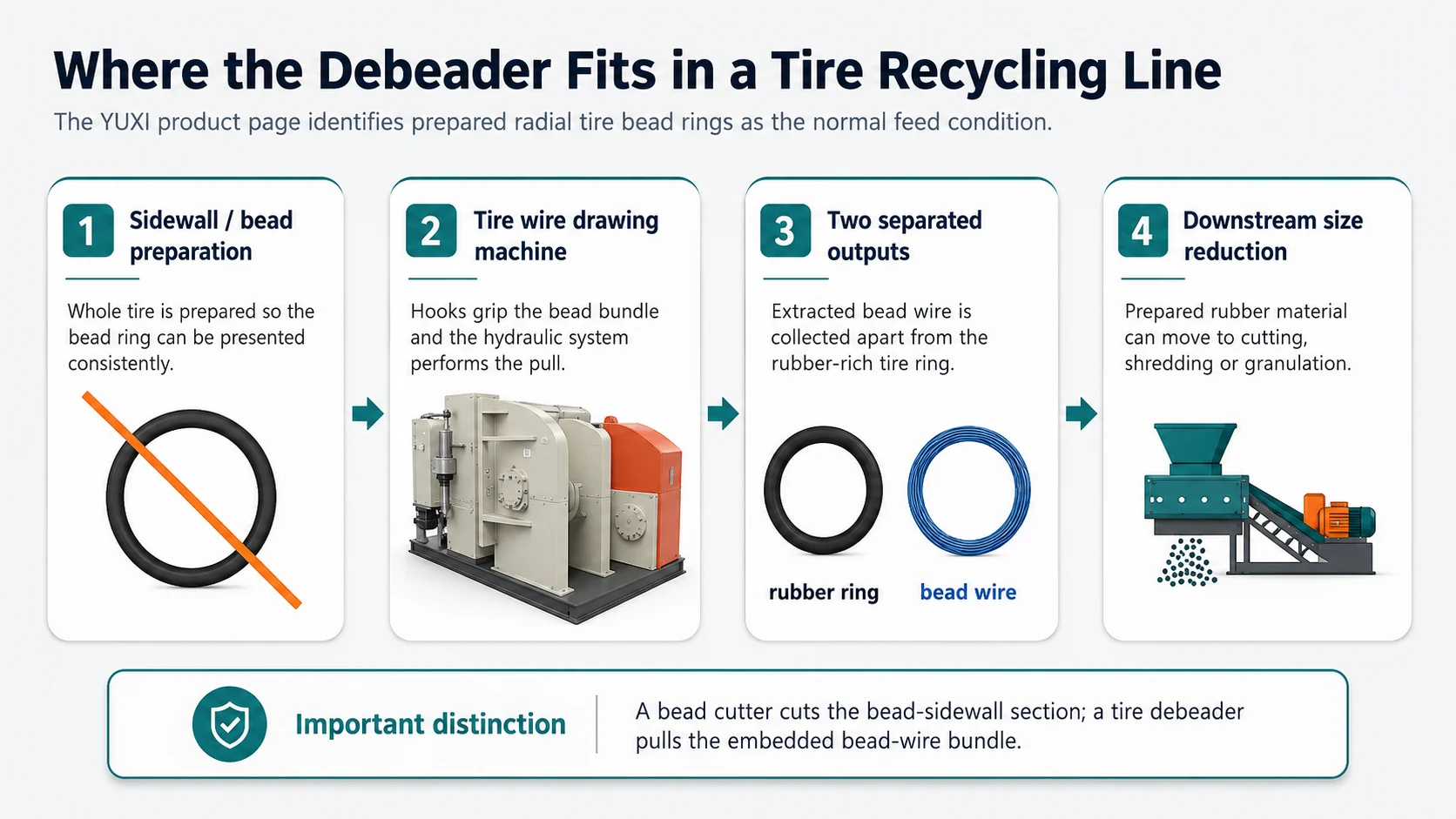
The YUXI product page places the machine before tire cutting, tire shredding, rubber-powder production or other pretreatment. A practical sequence can be:
Whole tire → sidewall/bead preparation → hydraulic debeading → tire cutting or shredding → further size reduction → steel and fiber separation
This is a process choice, not a universal rule for every recycling line. The value of debeading rises when concentrated bead wire is creating excessive cutter impact, wrapping, unstable feeding or a difficult steel fraction. The machine should be capacity-matched with the upstream preparation cell and the downstream cutter or shredder so that rings do not accumulate around the operator.
11. Safety Boundary: The Line of Pull Is a Danger Zone
A tire debeader combines heavy workpieces, hydraulic stored energy, a moving hook and a high-tensile wire bundle that can change shape as it releases. The point of operation and the direct line of pull must be treated as hazardous areas. The actual controls depend on the supplied machine, site risk assessment and local law.
For U.S. workplaces, OSHA’s general machine-guarding rule requires one or more guarding methods to protect people from point-of-operation, nip-point and moving-part hazards. OSHA also states that point-of-operation guarding should prevent body parts from entering the danger zone during the operating cycle.4 Servicing, clearing and adjustment can also involve hazardous electrical and hydraulic energy; OSHA’s lockout/tagout standard addresses unexpected energization, startup and release of stored energy during servicing and maintenance.5
Operate only from the approved position with all supplied guards and safety functions in service.
Keep people outside the hook path, workpiece movement zone and possible wire-release direction.
Do not hold, guide or clear the tire ring or extracted wire during an active cycle.
Do not search for hydraulic leaks by hand or alter pressure and valve settings without authorization.
Use the machine-specific isolation procedure before clearing, inspection, hook replacement or other servicing.
Plan separate collection so wire and rubber can be removed without reaching across the point of operation.
12. What a Buyer Should Verify Before Ordering
A working-principle article is useful only when it improves the request for quotation. Send YUXI enough material information to test the actual process rather than asking for a generic “tire debeader price.”
Feed and tire data
Passenger, bus, truck or mixed tire categories
Minimum and maximum tire diameter and width
Representative bead-area photos
Whether both sidewalls are already removed
Approximate ring weight and handling method
Process and project data
Required completed rings per hour or shift
Upstream cutting or preparation method
Downstream cutter, shredder or rubber line
Available operators and lifting aids
Workshop space, voltage and local standards
Ask for a video or test that records the complete cycle: incoming ring, loading, restraint, hook engagement, pull, extracted wire, remaining rubber ring, output clearing and reset. The test material should represent the tire categories expected in production.
Configure the Machine Around the Tire
Send YUXI representative tire photos, diameter range, prepared feed condition, target shift output, downstream process and local voltage. The team can then review the hook arrangement, hydraulic configuration and line position against the actual project.
What is the working principle of a tire wire drawing machine?
A hydraulic power unit moves one or more high-strength hooks through a controlled linear stroke. The hooks engage the steel bundle in a prepared tire bead ring, the cylinder applies pulling force, and the wire bundle separates from the surrounding rubber.
Does the YUXI tire wire drawing machine process whole tires?
YUXI’s public product page identifies prepared radial tire bead rings—especially rings with both sidewalls removed—as the normal feed condition. The exact acceptable feed must be confirmed for the selected configuration.
Is a tire wire drawing machine the same as a tire bead cutter?
No. A tire bead cutter cuts around the bead or sidewall area. A tire wire drawing machine, also called a tire debeader, grips and pulls the embedded bead-wire bundle.
Why does the machine use hydraulics?
The bead bundle is a high-strength steel component bonded into vulcanized rubber. Hydraulics provide a controllable linear pulling stroke and allow the machine frame, hook and cylinder to work as one force path.
Does a double-hook machine always process twice as many tires?
No. A double-hook arrangement may reduce repositioning or allow both bead areas to be handled in one setup, but real output also depends on loading, ring preparation, hook engagement, pulling stroke, release, sorting and operator workflow.
What information should a buyer send YUXI?
Send representative tire photos, tire category, minimum and maximum diameter, whether sidewalls are already removed, required shift output, downstream machines, local voltage and a short feed or current-process video.
References and Source Notes
U.S. Tire Manufacturers Association, “Tires 101,” tire construction and composition. Source
U.S. Tire Manufacturers Association, “How a Tire Is Made,” bead-hoop construction. Source
EPA/USTMA, “Scrap Tires: Handbook on Recycling Applications and Management for the U.S. and Mexico,” glossary and debeading note. Source
U.S. OSHA, 29 CFR 1910.212, General Requirements for All Machines. Source
U.S. OSHA, 29 CFR 1910.147, Control of Hazardous Energy. Source
Marie has 8+ years of experience in tire shredding and recycling equipment,with a focus on tire shredders,rubber recycling machines,TDF production,rubber crumb processing,and complete tire recycling systems.