




There are two very different ways to deal with the concentrated steel in a tire bead before the rest of the tire moves downstream. One route cuts the bead-rich ring away first and then sends that ring to a dedicated wire-separation step. The other route uses hydraulic wire drawing to pull bead steel from a compatible prepared tire or bead ring. The machines may appear to solve the same problem, but they create different intermediate materials, handling duties, bottlenecks and acceptance evidence.
The useful comparison is therefore: which complete route delivers the required tire-preparation state, recovered-steel condition and downstream rubber condition at the lowest practical burden for your actual tire mix? YUXI’s waste tire bead cutting machine is designed to isolate the bead or bead-sidewall section from the main tire body. The removed bead section still contains rubber around the steel and may need dedicated bead-wire separation when cleaner steel recovery is required.
Quick Answer: Choose the Route by Feed State and Test Boundary
Bead cutting + wire separation is a two-stage material route. It first converts a tire into a main tire body plus one or more bead-rich sections; the bead-rich sections then become the feed to a separate steel/rubber separation stage. This gives the plant a clearly isolated intermediate stream, but it also creates another transfer, buffer, machine duty and maintenance point.
Direct wire drawing removes the bead wire by pulling it from a compatible prepared tire or ring in one main extraction stage. It can remove the separate bead-ring separator from the route. The approved incoming geometry still has to match the machine and hook/clamp arrangement.
Do not select either route from a catalog cycle time. Compare complete-route accepted throughput, operator minutes, interventions, recovered-steel cleanliness, steel left in rubber, retained material and the condition required by the next process.
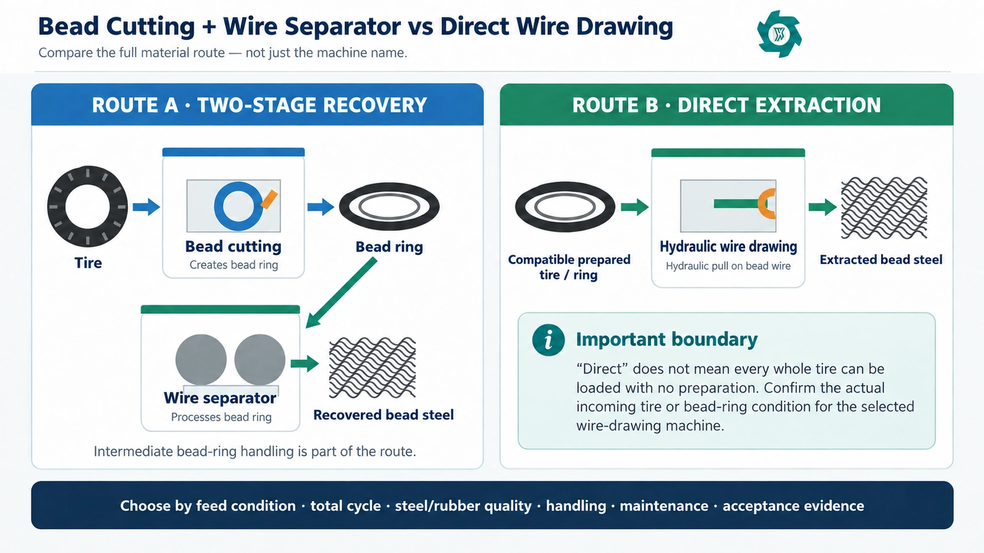
Why This Is Not Just Another Bead Cutter vs Debeader Comparison
A basic bead-cutter-versus-debeader decision asks what each machine physically does. The more difficult procurement question is whether the plant should use a two-stage bead-ring recovery cell or a direct hydraulic extraction route.
For projects that already require early bead-steel recovery, the engineering decision is whether to build a two-stage bead-ring recovery cell or use a direct hydraulic extraction route. That changes the engineering question from “cut or pull?” to “what material moves between stations, what limits the rate, and what evidence proves the chosen route actually works?”
That distinction matters because tire beads are not loose scrap wire. The U.S. Tire Manufacturers Association describes the bead as steel-wire hoops embedded into the tire structure, which helps explain why cutting, gripping, pulling or stripping this bonded steel-and-rubber region behaves differently from handling loose recovered steel.1 Tire construction and preparation therefore need to be fixed before the two recovery routes are compared.
First Define What Enters the Machine
The highest-value specification sentence in this comparison is not a motor rating. It is the description of the incoming material. A quote that says only “truck tire” leaves too much open. Is the tire whole? Has one sidewall been removed? Are both sidewalls removed? Is there a bead-sidewall ring on the floor? Has the ring been cut or opened? Can the hook reach the bead bundle without the operator forcing the workpiece into an unstable position?
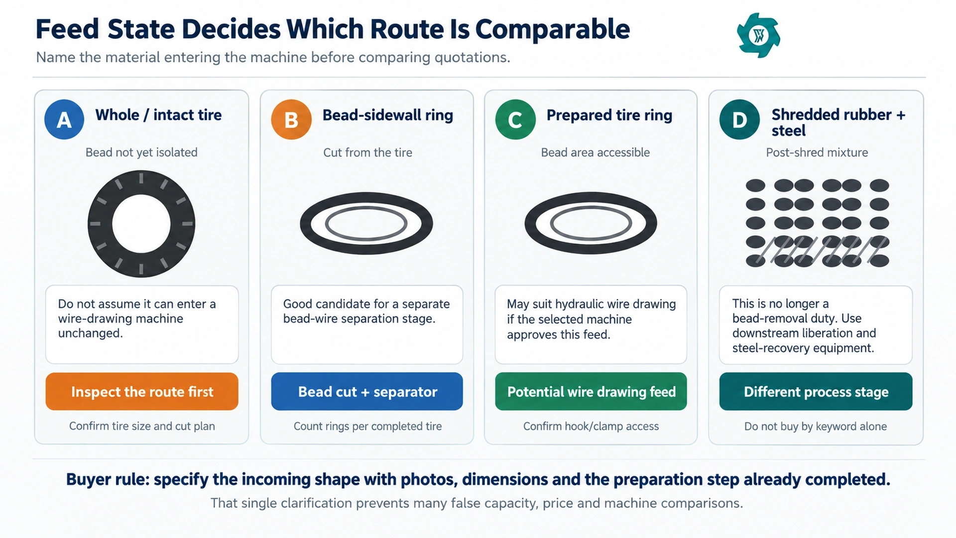
A separator that receives a cut bead ring is doing a different job from magnetic equipment later in a shredded or granulated rubber line. For this comparison, wire separator means a dedicated stage that receives the bead-rich section created upstream and separates the concentrated bead steel from that rubber-rich intermediate.
Route A: Bead Cutting + Dedicated Wire Separation
Route A divides the work into two transformations. The first station isolates the bead-rich material from the tire body. The second station works on that isolated material to recover the bead steel and create a rubber-rich remainder. The main tire body can move toward the next size-reduction step while the bead-ring stream is handled separately.
What the route adds
The extra separation stage is not only another motor or another purchase line. It adds an intermediate product, a transfer method and a buffer question. The plant must decide where removed bead rings land, how they are counted or weighed, whether they are carried manually or conveyed, how much temporary storage is acceptable, and what happens when the separator stops while the bead cutter continues.
A clearly isolated bead-ring stream is easier to sample and audit than steel that is mixed into later shred fractions. It also lets the plant operate the bead cutter and separator as separate cells when staffing or downstream demand changes. But the same separation of duties can create hidden work if rings are repeatedly lifted, stacked, tangled, carried across traffic lanes or rehandled before the second machine.
What the route must prove
A two-stage route should prove more than “the cutter completed the tire.” It has to show that the bead-ring output is suitable for the separator, the separator can keep up with the ring generation rate, the recovered steel meets the agreed cleanliness check, and the rubber-rich remainder can be returned to the intended material route without becoming a side pile that nobody has priced into the project.
Route B: Direct Hydraulic Wire Drawing
Route B concentrates the bead-steel removal duty into a pulling process. The prepared tire or bead ring is positioned, the hook engages the bead bundle, hydraulic force extracts the wire, and the outputs are collected.
The attraction is that fewer dedicated recovery stages can mean less floor space between bead isolation and steel collection, fewer transfers and fewer separate wear interfaces. But that advantage exists only when the feed can be prepared and presented consistently. A machine that pulls wire quickly can still become the bottleneck if operators spend most of the cycle wrestling with flexible rings, finding a usable engagement point, clearing mixed tire sizes or moving heavy tire material into and out of the work zone.
What the route must prove
Do not judge this route from the hydraulic pull alone. Time the full cycle: preparation already required by the route, loading, positioning, hook engagement, pulling, release, discharge, steel collection and any rework.
The Comparison Table Buyers Actually Need
| Decision point | Bead cutting + wire separator | Direct wire drawing | What to verify |
|---|---|---|---|
| Incoming material | Tire suitable for bead cutting; separator receives the resulting bead-rich section. | Compatible prepared tire or bead ring with usable bead access. | Photos, dimensions and preparation state before each machine. |
| Number of main recovery stages | Two: bead isolation, then bead-wire separation. | One main extraction stage after required preparation. | Do not hide preparation or material transfer outside the quoted boundary. |
| Intermediate material | Bead rings or bead-sidewall sections must be moved and buffered. | Less bead-ring transfer between dedicated recovery machines. | Floor handling, container position, queue and operator travel. |
| Capacity risk | Separator or ring transfer can lag behind the bead cutter. | Preparation, hook engagement or handling can lag behind the pull stroke. | Complete-route elapsed-time test. |
| Recovered steel | Produced after the dedicated bead-ring separation step. | Produced directly by hydraulic extraction. | Rubber residue on steel and repeatability across tire families. |
| Rubber-side output | Main tire body plus rubber-rich bead remainder. | Prepared rubber remainder after extraction. | Steel left in rubber and the actual downstream receiving route. |
| Maintenance points | Cutting interface plus separator working parts and two material-handling interfaces. | Hook/clamp/pulling system plus hydraulic and workpiece-handling interfaces. | Wear inspection points, access and spare-part plan. |
| Best-fit evidence | Useful when the plant wants a separately controlled bead-ring stream and can justify the extra stage. | Useful when compatible preparation is stable and fewer recovery transfers genuinely reduce work. | Same representative batch, same acceptance definitions. |
Capacity: Normalize the Whole Route, Not One Machine
Capacity is where these routes are most often compared badly. A supplier may quote tires per hour for the bead cutter, rings per hour for the separator and cycles per hour for the wire-drawing machine. None of those numbers can be compared until the counting unit and process boundary are aligned.
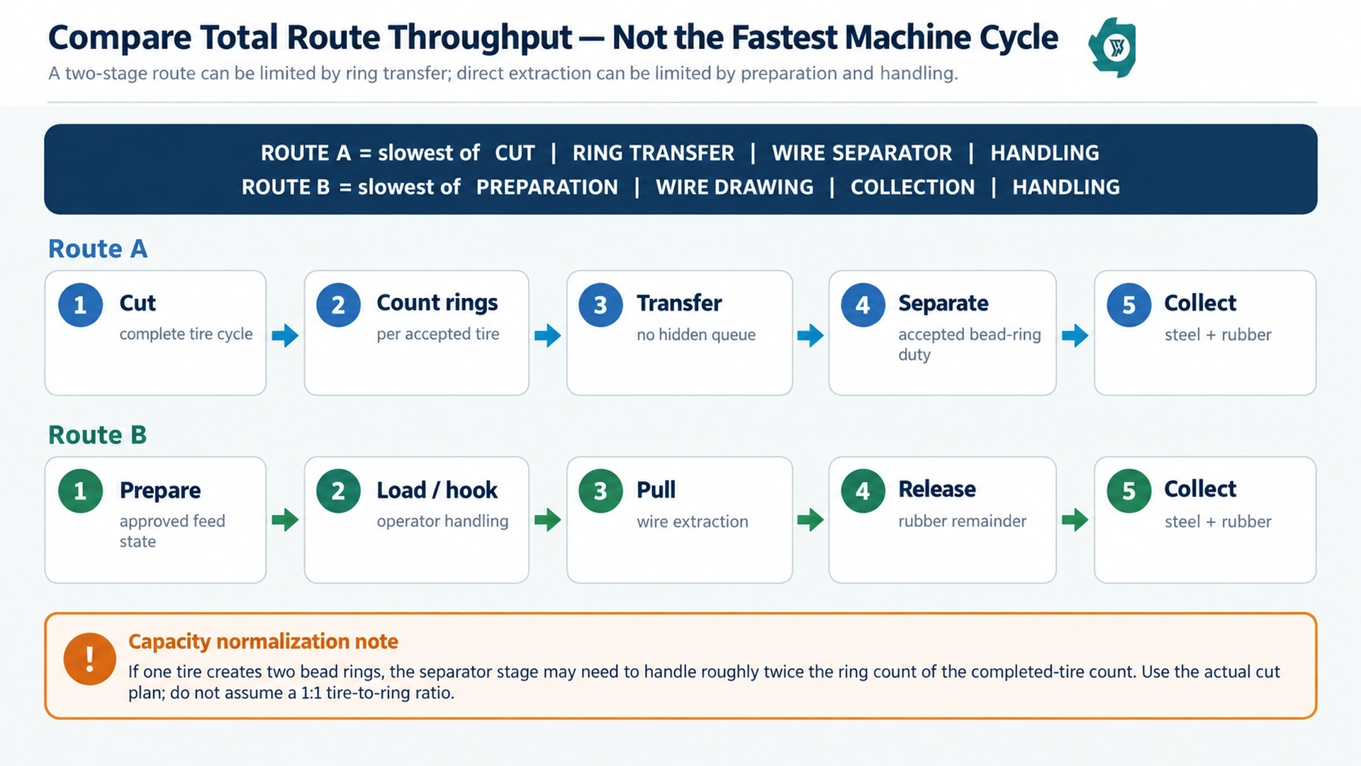
For Route A, think of the accepted rate as the slowest of four duties: bead cutting, ring transfer/buffer handling, wire separation and operator/material handling. For Route B, use the slowest of required preparation, wire drawing, discharge/collection and handling. If any one of those stages queues material continuously, the headline rate of the faster machine is not the line rate.
If the selected cut plan produces two separate bead rings from each completed tire, then a bead cutter completing 50 tires per hour would create a theoretical separator duty of 100 rings per hour. If the actual cut plan produces a different intermediate form, use the real count from the test.
The same discipline applies to mass. If one quote reports tons per hour and another reports tires per hour, weigh a representative batch rather than applying a guessed tire mass. For a mixed passenger/truck stream, record the mix. Otherwise a route tested on lighter tires can look artificially faster when converted into “pieces per hour,” while a route tested on heavier tires may look slower even though the mass rate is higher.
Passenger, Truck and OTR Tires Can Move the Crossover Point
Passenger and light-truck tires may favor rapid repetitive handling if the feed is uniform and the operator can present the prepared material consistently. In that situation, every extra ring transfer becomes visible in labor minutes. But a two-stage route can still make sense when the plant wants a highly controlled bead-rich side stream or when its existing workflow already isolates sidewalls efficiently.
Truck and bus tires deserve separate tests because the bead region and sidewall handling burden are greater than with typical passenger tires. A route that looks balanced on light tires can develop a queue when heavy rings take longer to reposition, when pulling engagement varies, or when the separator requires more controlled feeding.
Large agricultural, industrial or OTR tires should not be forced into a passenger/truck assumption. The first practical question may be how the tire is opened or sectioned safely enough to expose the required region. Where geometry reduction is needed before downstream processing, a hydraulic tire cutting machine can be a separate preprocessing duty. Final equipment selection still depends on the real diameter, width, reinforcement and approved cut plan.
Recovered Steel Quality: Measure Both Sides of the Separation
The plant should check rubber remaining on the recovered steel and steel remaining in the rubber-side output. Improving one side by sacrificing the other may only move the loss.
This is especially important because the input bead-steel mass is usually not known from a simple tire weigh-in. A supplier cannot honestly claim a precise “bead steel recovery percentage” merely from the mass of steel collected unless the actual bead-steel mass entering the test is also established. For many factory tests, the more defensible approach is to:
- weigh recovered bead steel separately;
- sample and quantify rubber residue on that steel using an agreed method;
- sample the rubber-side output for remaining bead steel;
- record any unprocessed or reworked bead sections;
- reconcile all material streams rather than hiding missing mass as “loss.”
Downstream product requirements change how much front-end steel removal is worth. The U.S. EPA’s tire-crumb discussion notes that crumb production commonly uses magnets and other separation steps and describes the process as removing nearly all steel and fabric from tire rubber.2 This downstream requirement shows why a project targeting clean rubber granulate should evaluate bead removal as part of the complete steel-control strategy.
Do Not Lose the Rubber Side of the Mass Balance
Bead steel gets attention because it is visible and saleable, but the rubber around the bead has value and handling cost too. Route A creates a main tire body and a separate bead-derived rubber stream after steel separation. Route B leaves a rubber remainder after the wire is pulled. Both need a defined destination.
If the next step is primary size reduction, ask whether the rubber remainder can be fed consistently to the tire shredder machine without manual trimming, tangled wire tails or awkward pieces. If the project targets a more steel-controlled downstream product such as a wire-free rubber mulch line, the front-end route should be judged by how much steel burden and irregular material it leaves for later liberation and magnetic separation.
Labor: Count Touches, Not Operators Listed in the Quotation
Count what the operator actually does during a full cycle. Route A can require tire loading, bead-ring removal, ring stacking or transfer, separator feeding, steel discharge and rubber discharge. Route B can require feed preparation, positioning, hook engagement, pulling-cycle supervision, release, steel collection and rubber handling.
Use operator-minutes per accepted tire or per accepted tonne. Include repeat positioning, clearing normal non-product material and routine container changes. Keep maintenance and abnormal repair separate so the production labor figure does not become inflated by one unusual breakdown.
Maintenance: Two Stages Do Not Automatically Mean Twice the Cost
Route A has more distinct working interfaces: a cutting tool, tire positioning/rotation, the bead-ring separator working parts, and the transfer points between them. Route B removes the dedicated bead-ring separator from the comparison, but it puts more emphasis on the hook, clamping/positioning area, pulling structure and hydraulic system.
The correct maintenance comparison is not the number of components. Compare the work that actually interrupts production: inspection frequency, accessible wear parts, replacement time, normal cleaning, adjustment checks, lubrication points, spare parts held on site and the number of interventions that stop the accepted route.
Ask suppliers to identify wear parts without inventing a universal replacement interval. Cutter life, hook wear and separator working-part life depend on tire family, steel exposure, contamination, alignment, operation and maintenance.
Safety and Material Handling Change With the Route
Both routes expose operators to moving machinery and stored energy. A bead-cutting station has a cutting interface and rotating/positioning workpiece. A bead-ring separator may have in-running nip or crushing zones depending on its design. A wire-drawing machine applies high pulling force to a workpiece that can deform as steel releases.
OSHA’s general machine-guarding rule requires guarding to protect operators and other employees from hazards such as point-of-operation, ingoing nip-point and rotating-part hazards.3 Servicing and maintenance also require control of hazardous energy under the applicable energy-control program; OSHA 29 CFR 1910.147 addresses lockout/tagout requirements for such work.4
Installed Cost: Compare the Cell, Not the Machine Invoice
Route A normally contains more dedicated recovery equipment, but machine count alone still does not equal installed cost. Route B may need stronger preparation fixtures or additional upstream cutting, while Route A may need an intermediate bin, short conveyor, guarded transfer or more floor area.
For operating cost, compare the variables that repeat:
- operator-minutes per accepted tire or tonne;
- energy measured at the agreed equipment boundary;
- wear parts and normal consumables;
- planned inspection and maintenance time;
- unplanned interventions and rework;
- material value lost in rubber stuck to steel or steel left in rubber;
- downstream wear or cleaning burden created by the front-end result.
When the Two-Stage Route Deserves Serious Consideration
- the bead cutter already fits the tire-preparation sequence needed by the main tire body;
- the plant wants bead rings collected as a controlled, auditable intermediate stream;
- the separator can be matched comfortably to the actual ring generation rate;
- the layout can move rings directly without repeated manual lifting or long travel;
- the rubber-rich bead remainder has a defined return path;
- maintenance access and buffering let one station stop briefly without losing the whole shift.
These are decision conditions, not a claim that the route is universally superior. If the ring transfer becomes a labor-intensive side process or the separator cannot follow the cutter, the apparent control advantage turns into work-in-process inventory.
When Direct Wire Drawing Deserves Serious Consideration
- a repeatable approved feed state with reliable bead access;
- manageable tire/ring handling for the actual operator and lifting arrangement;
- stable hook engagement across the commercial tire mix;
- a recovered-steel and rubber result that meets the agreed acceptance checks;
- less intermediate inventory and fewer material transfers in the real layout;
- a maintenance plan that supports the hook, hydraulic and restraint duties.
The route loses its simplicity advantage if “direct” extraction still requires several unpriced manual preparation steps before every pull. Put those steps inside the stopwatch and the layout before deciding.
Use a Common FAT Boundary to Compare the Routes
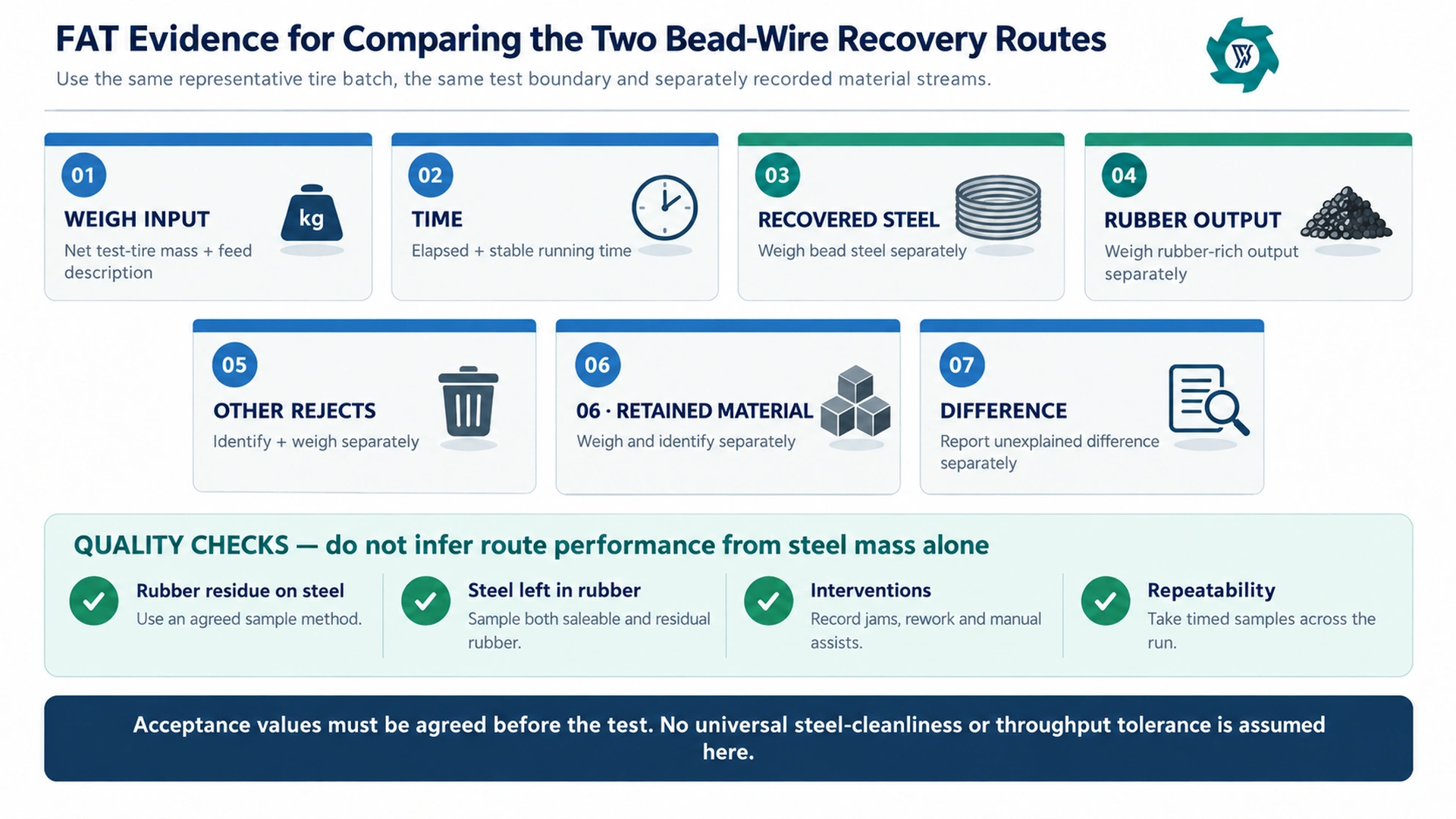
The strongest comparison is a controlled factory acceptance test using representative project tires. The two routes do not need identical machines, but they do need the same rules for what enters the test, what time is counted and what outputs are reported.
1. Lock the feed description
Photograph and list the tire families, markings, size range, visible condition and preparation state. If the batch contains passenger and truck tires, report the mix. If one route requires an upstream cut before the timed extraction test, state whether that preparation is inside or outside the test boundary.
2. Weigh the input and each output separately
Record net test-tire input. Then weigh recovered bead steel, rubber-rich output, other rejects and material retained in the route separately. State unexplained difference separately.
3. Record both elapsed time and stable running time
Elapsed time captures the complete operational burden. Stable running time helps diagnose the active processing period. Report both so a fast active stroke cannot hide long loading, ring transfer or repeated re-positioning.
4. Record interventions
Log stops, manual assists, repeated pulls or passes, material that has to be reworked, and any condition that would not be acceptable in normal production. A demonstration that reaches the target only because an operator repeatedly intervenes is not the same as a stable route.
5. Sample the products
Use an agreed method for rubber residue on recovered steel and steel left in rubber. Take samples at more than one point in the test so the final result does not depend on one attractive end-of-run sample.
6. Agree acceptance values before the test
There is no universal throughput, rubber-on-steel or steel-in-rubber tolerance that can be inserted here without the project specification. Write the acceptance limits and sampling method into the RFQ or FAT protocol before the machine is tested.
RFQ Checklist: Send the Same Data to Every Supplier
Feed dossier
Tire photos, markings, passenger/truck/OTR mix, diameter, width, approximate unit mass and current preparation state.
Route boundary
State whether upstream sidewall cutting, bead-ring cutting, lifting and material transfer are included in the supplier’s duty.
Production target
Required accepted tires/h, tonnes/shift or annual volume, plus operating hours and expected tire mix.
Output condition
Recovered-steel cleanliness target, steel allowed in rubber, and the next process receiving the rubber remainder.
Site constraints
Workshop dimensions, operator access, container or conveyor position, lifting method, voltage/frequency and utilities.
Acceptance evidence
Representative test batch, weighing, timing, sampling, intervention log, retained material and unexplained difference.
Buyer Mistakes That Make the Comparison Useless
Comparing “two machines” with “one machine” before defining preparation
Route B may look simpler on paper, but an unpriced preparation step can sit outside the quotation. Route A may look more complex, yet the bead cutter may already be required for the main tire-body route.
Using the cleanest steel photo as the acceptance test
Product quality must be sampled. One hand-picked wire bundle says nothing about repeatability or the steel left behind in rubber.
Comparing cutter tires/h with separator rings/h
The units describe different things. Convert through the actual number of intermediate ring pieces per completed tire and verify the buffer between stages.
Ignoring the material that remains inside or between machines
Retained bead sections, wire, rubber and offcuts matter to the mass balance. Weigh or identify them before calculating a yield or loss figure.
Assuming early bead removal means the tire is now wire-free
The bead is only one steel-containing region. Steel belts and other reinforcement can remain in the tire carcass and are handled later by the designed liberation and separation process.
Letting the supplier choose the easiest test tires
A route that passes on a small uniform batch may fail on the project mix. Use representative tires and state the mix in the test record.
Final Selection Rule
Choose bead cutting + wire separation when the isolated bead-ring stream improves control, the second stage can keep up, the material transfer is practical and the full installed cell produces the required steel/rubber result with acceptable labor and maintenance.
Choose direct wire drawing when the approved preparation state can be produced consistently, the pulling station handles the real tire mix without excessive intervention, and removing the separate bead-ring separation stage actually reduces total route work—not just the equipment count on the quotation.
If the result is still unclear, put the two candidate routes on the same representative batch and lock the time and mass-balance boundary, and compare accepted output plus product quality. The better route is the one that survives that normalization.
FAQ
Is bead cutting plus a wire separator the same as direct wire drawing?
The two-stage route first isolates a bead-rich ring or sidewall section and then separates steel from that intermediate material. Direct wire drawing uses a hydraulic pulling action to extract bead wire from a compatible prepared tire or bead ring without that separate bead-ring separation stage.
Does direct wire drawing mean I can load any whole tire with no preparation?
The incoming tire condition must match the selected machine. Tire wire drawing equipment commonly works with prepared radial tire bead rings, especially material that has already undergone sidewall preparation. Confirm the exact tire or ring geometry before comparing capacity.
Which route gives cleaner recovered steel?
Neither route should be assumed cleaner without a test. Compare rubber residue on recovered steel and steel remaining in the rubber output using an agreed sampling method on the same representative tire batch.
How should I compare capacity between the two routes?
Use complete-route accepted output over elapsed time. For the two-stage route, include bead cutting, ring transfer or buffering, wire separation and handling. For direct wire drawing, include required preparation, loading, pulling, release and collection. The slowest stage limits the practical rate.
What should be included in a factory acceptance test?
Define representative tires, feed preparation, the test boundary, elapsed and stable running time, weighed input, recovered steel, rubber output, other rejects, retained material and unexplained difference. Also record interventions and take repeatable product-quality samples.
What information should I send for route selection?
Send tire photos and markings, tire family and size range, the condition of the tire entering pretreatment, expected hourly or shift volume, downstream product target, steel-cleanliness requirement, available labor, workshop layout, voltage and frequency, and the acceptance criteria you want tested.
Compare the Route With Your Actual Tires
Prepare tire photos and markings, size range, current preparation state, expected volume, downstream product target, steel-cleanliness requirement, available labor and workshop layout. Use those details to compare the complete route instead of a single machine specification.
Engineering References
- USTMA tire. Bead-wire construction context.
- EPA crumb. Steel and fabric removal context.
- OSHA guarding. Machine-guarding principles.
- OSHA LOTO. Hazardous-energy control.