Crumb Rubber Manufacturing Process: Waste Tires to 0–5 mm
Follow the material—not just the machine names—as waste tires move through coarse shredding, steel liberation, granulation, screening, magnetic recovery and fiber separation to become a controlled 0–5 mm crumb-rubber product.
The process becomes easier to troubleshoot when every stage has a defined incoming material condition and a measurable outgoing condition.
A clean bag of 0–5 mm crumb rubber makes the production route look shorter than it really is. The product has no obvious bead bundle, no long belt wire, little visible textile and no oversized tire chip. Yet all of those materials were present in the original tire. The manufacturing job is therefore not simply “grind the tire smaller.” It is to reduce size while progressively opening the composite tire structure and removing the reinforcement at the right stage.
How Waste Tires Become 0–5 mm Crumb Rubber
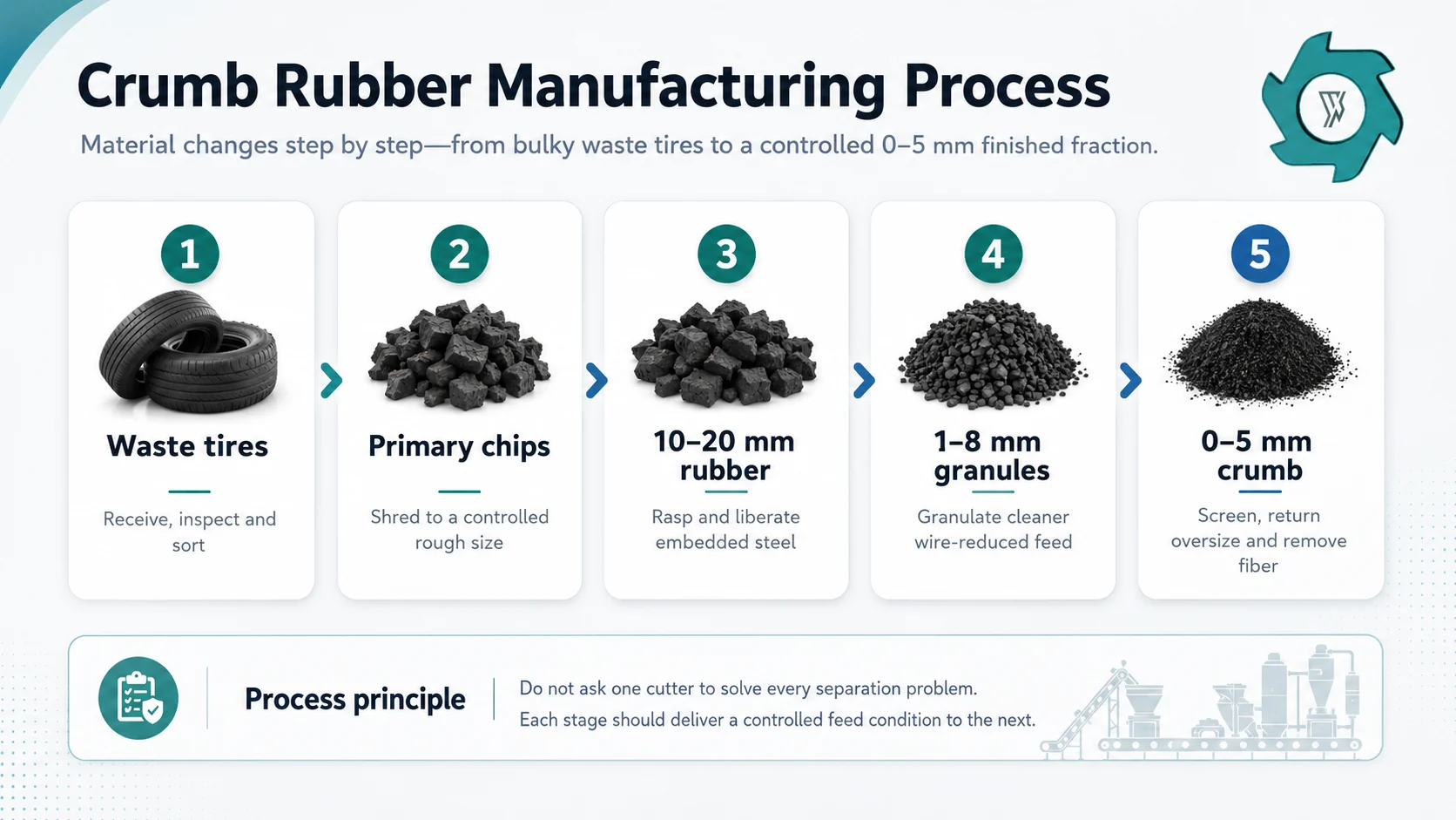
In an ambient mechanical line, waste tires are first inspected and prepared, then reduced to coarse chips by a primary shredder. A tire rasper cuts the chips further and opens the rubber around embedded steel. Magnetic separators recover the liberated steel before the cleaner rubber reaches a granulator. The granulator reduces the material to small rubber particles, grading screens separate the required fraction and return oversize for another pass, a later magnetic stage catches newly exposed fine steel, and air separation removes loosened textile fiber. The accepted stream is then sampled and verified as the specified 0–5 mm product.
Step 1: Receive, Inspect and Prepare the Waste Tires
The crumb-rubber manufacturing process begins at receiving, not at the shredder. Tire class, outside diameter, width, weight, bead construction, belt reinforcement and contamination change how easily the feed can be captured and reduced. A plant that processes mostly passenger tires behaves differently from one that receives a high share of truck tires. Agricultural and OTR tires may require a separate preparation route because their dimensions and reinforcement can exceed the normal feed envelope of the selected equipment.
We normally ask for representative tire photos and a rough feed mix before finalizing the front end. This is not paperwork for its own sake. A large tire forced into equipment designed around smaller tires can create intermittent feeding, repeated reversals and unsafe manual intervention. The process should be designed around the largest approved feed, not the easiest tire in a sales video.
What should be removed or isolated before production?
Mounted rims, pressurized tires, excessive soil, stones, chains, tools, liquid-filled tires and unknown industrial contamination need a defined receiving rule. Bead treatment or tire sectioning may also be required depending on tire size and the selected line. The exact preparation route can vary; what should not vary is the handoff requirement: the next machine must receive a feed shape, mass and contamination level it can handle repeatedly.
For readers who need the upstream route in more detail, the industrial rubber-mulch process guide explains the whole-tire-to-10–20 mm stage that precedes fine crumb production.
Step 2: Primary Shredding Changes the Tire Geometry
A whole tire is difficult to meter because it is bulky, elastic and ring-shaped. Primary shredding changes that geometry into rough chips that can move on conveyors and enter a secondary cutter more predictably. This is the first major transformation, but it is still coarse processing. The rubber, steel belts, bead reinforcement and textile structure remain substantially mixed together.
YUXI’s current crumb-plant configuration uses about 50 mm rubber blocks as a primary-shredder process reference, while the rasper is specified to accept rough tire shreds below 100 mm. These figures describe different parts of the machine-to-machine handoff rather than one exact particle dimension. Real tire chips are irregular, so feed geometry, maximum piece size and steel condition matter more than expecting every discharged piece to measure exactly 50 mm.
The FHWA describes scrap-tire size reduction as a sequence in which steel and fiber are separated as particle size is progressively reduced; it also distinguishes granulator and finer grinding routes by the particle ranges they produce.1 That is why primary shredding should be judged by what it prepares—not by whether it already resembles finished crumb.
Common mistake: comparing the shredder’s maximum feed rate with the final crumb-plant capacity. Coarse chips can be produced faster than a tight 0–5 mm finished fraction if the downstream granulator and return loop are doing much more cutting work.
Step 3: The Rasper Reduces Size and Liberates Embedded Steel
The tire rasper sits at the most important transition in the line. Rough shredder output still contains steel cords locked inside thick rubber pieces. The rasper repeatedly cuts and opens those pieces, reducing them toward a smaller chip while exposing the steel so a magnetic separator can recover it. On YUXI’s current process page, the rasper stage is described around 10–20 mm wire-free rubber chips as the downstream target direction.
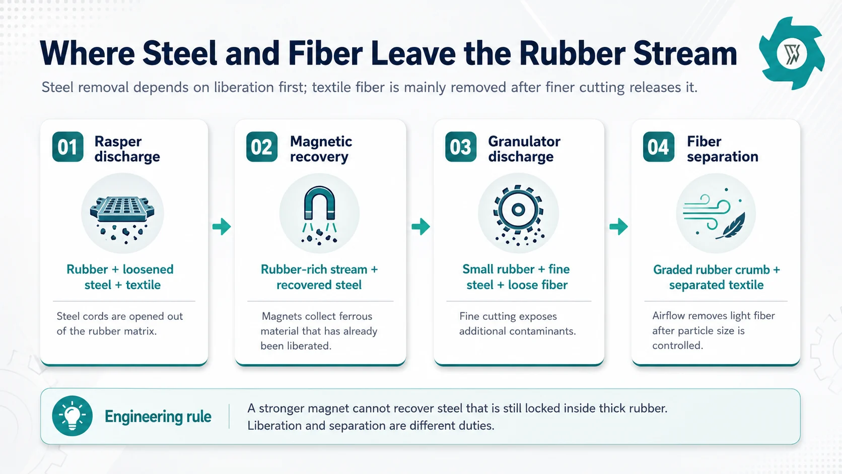
“Wire-free” should not be interpreted as a magic event inside the cutting chamber. The rasper’s first duty is liberation. The following magnetic stage performs recovery. If thick rubber still encapsulates steel, a stronger magnet cannot pull that steel through the rubber matrix. This is one reason the mechanical condition of the rasper—knife sharpness, clearances, screen condition and steady feed—shows up later as a magnetic-separation problem.
Steel recovery and fiber recovery occur at different points because the two contaminants require different liberation and separation mechanisms.
Step 4: First Magnetic Separation Protects the Fine-Reduction Stage
Once the rasper has opened the rubber around the steel, magnetic separation can recover a large share of the ferrous material. Magnet performance depends on more than magnetic strength. Burden depth, belt speed, material presentation, wire shape and cleaning condition all matter. A deep surge of rubber can physically bury wire under nonmagnetic material; a long wire loop can also tangle with rubber and carry it past the intended recovery point.
The process objective is not merely to produce a steel by-product. Removing liberated wire before the granulator protects the finer cutting stage. Fine-reduction knives and screens are more sensitive to unexpected steel, and wire can wrap, chip cutting edges or increase heat and load. Separating the steel at the first practical point reduces that risk.
This also explains why a plant may use more than one magnetic pass. The first pass removes steel exposed during rasping. Later granulation can break open smaller rubber pieces and reveal short steel fragments that were not previously available to the magnet.
Step 5: The Granulator Turns Prepared Chips into Small Rubber Particles
After the main steel-liberation and magnetic-recovery duty, the rubber stream is ready for finer cutting. The YUXI Tire Rubber Crumb Plant describes 10–20 mm wire-free chips as granulator feed and a 1–8 mm rubber-pellet range as a typical granulator-stage output. The complete system highlights 0–5 mm as the main finished range after grading, return processing and final separation. Those two numbers are not contradictory: one describes a machine-stage range; the other describes the collected finished fraction after classification.
Inside the granulator, screen opening, knife condition, knife gap, feed stability and residence time interact. Smaller openings generally require more cutting before a piece can leave the chamber. Dull knives can stretch and heat rubber rather than cut cleanly. An unstable feed can alternate between empty running and overloaded cutting, creating a wider particle distribution and less predictable motor load.
This is where the term ambient mechanical process matters. The rubber is size-reduced mechanically at normal plant temperatures rather than being frozen for brittle fracture. FHWA literature distinguishes ambient granulator-type processing from cryogenic techniques and notes that particle shape and size can differ by process.1 A buyer should therefore qualify material by the actual application specification rather than assuming all “crumb rubber” is interchangeable.
Step 6: Screening Creates the Product Boundary—and the Return Load
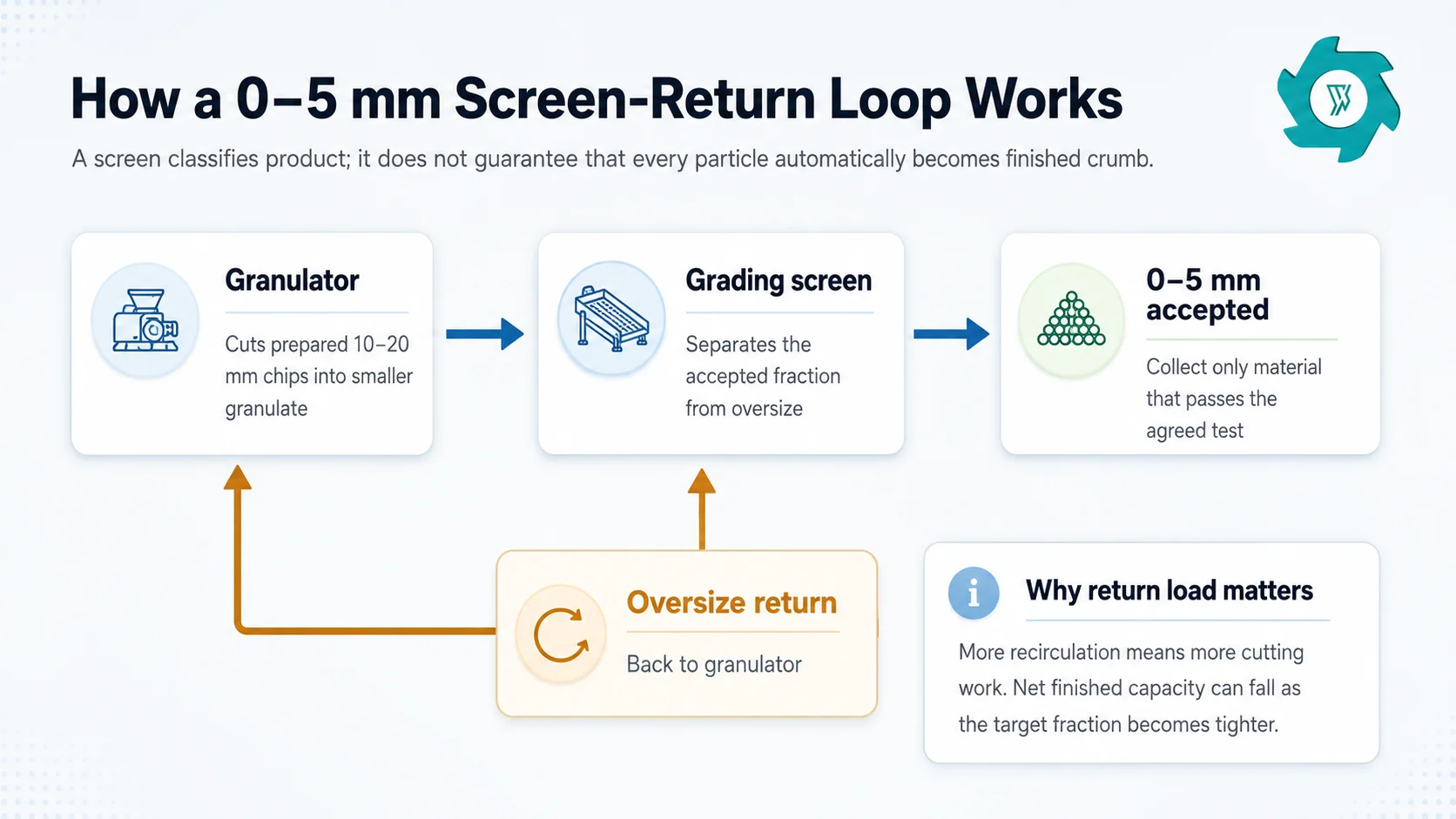
A granulator does not automatically produce a single finished size. It produces a distribution. The grading screen decides which fraction leaves the line and which fraction goes back for another cutting pass. This is why the EPA description specifically mentions sifting screens that return oversize pieces to the reduction process.2
The accepted product is only the material that passes the agreed grading rule; oversize remains part of the circulating load until it is cut again.
This point is easy to miss when comparing quotations. Two suppliers may both list a 2 t/h granulator, but one quote may mean 2 t/h entering the cutter while the other may be discussing 2 t/h of accepted final product. If a tight screen returns a large share of material, the internal circulating load can be much higher than the finished output leaving the plant.
Screen condition matters as well. Worn or damaged openings may allow oversized pieces to pass. Blinded openings reduce effective area and increase retention. Changing the screen without checking the return conveyor, surge capacity and granulator load can move the bottleneck rather than solve it.
Step 7: Secondary Magnetic Recovery and Fiber Separation Finish the Cleaning Work
Fine granulation exposes contamination that was previously hidden. Short steel fragments may become accessible to a second magnetic stage. Textile reinforcement also becomes looser as the rubber particles get smaller. An air-based fiber separator can then remove the lighter textile fraction from the denser rubber granules.
Airflow has to be tuned to the actual fraction. Too little air leaves fiber in the rubber. Too much air can carry valuable fine rubber into the fiber discharge. Moisture, dust, feed surges and mixed particle sizes can all change the separation behavior. For this reason, the best operating point is found with representative material and verified by sampling both the product and reject streams.
The EPA’s current tire-crumb Q&A describes the same general mechanism: magnets remove wire and other metal contaminants, while air separators remove fabric.2 In a plant contract, however, “clean” should be translated into measurable steel and fiber limits rather than left as a visual adjective.
Step 8: Define “0–5 mm” as a Measurable Product Specification
A label such as 0–5 mm is useful for orientation, but it is not a complete acceptance specification. Tire-derived rubber particles are irregular. A buyer may care about the percentage retained on selected sieves, the maximum oversize, fines below a lower threshold, loose steel, textile content, moisture, dust, bulk density or packaging. The required combination depends on the downstream use.
CalRecycle’s statutory definition provides a useful outer boundary: it defines crumb rubber as rubber granules derived from waste tires that are 6 mm or smaller.3 ASTM D5603 classifies recycled vulcanizate rubber around particle-size distribution and origin, while ASTM D5644 provides a standardized particle-size distribution test method for recycled vulcanizate particulate rubber.45 These references reinforce a basic procurement principle: a screen opening is not the same thing as a verified product distribution.
A practical 0–5 mm purchase specification should state
The sieve or classification method used to verify the fraction.
The permitted percentage above 5 mm and any required lower-size or fines limit.
Maximum metal content and how it is sampled or detected.
Maximum textile-fiber content, reported separately from metal.
Moisture or dust limits if they matter to packaging or downstream processing.
The sampling point, sample mass, sampling frequency and pass/fail rule.
The net finished-product throughput expected while meeting all of the above.
If the commercial decision is still whether to stop at 10–20 mm mulch or continue to fine crumb, the rubber mulch vs crumb rubber guide covers that product-boundary decision without turning this article into another market comparison.
Step 9: Understand Why Finer Finished Crumb Changes Real Capacity
Capacity falls into at least three different numbers: material entering the line, material circulating inside the cutting-and-screening loop, and saleable product leaving the final collection point. They are not interchangeable. A line can appear busy while the finished-product conveyor is slow because oversize is repeatedly returning for another pass.
The main variables are predictable. A smaller or tighter fraction increases cutting work. A higher truck-tire share can increase reinforcement and wear duty. Dull knives change the energy needed per tonne. Contamination causes stoppages. A partly blinded screen increases residence time. Poor fiber separation may force reprocessing or product rejection. Even when every motor is sized correctly, the final accepted throughput can differ from a broad “feed capacity” number.
Better capacity wording: “Please state accepted finished tonnes per hour at the agreed 0–5 mm particle distribution and impurity limits, using our representative tire mix, with normal oversize return included.” This is more useful than asking only for the largest feed rate shown in a brochure.
Step 10: Verify the Complete Line with a Factory Acceptance Test
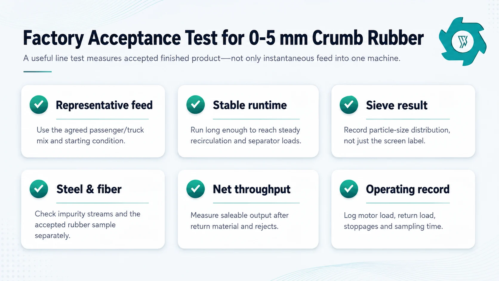
A short video of rubber falling from a conveyor is not a process test. For a 0–5 mm project, the FAT should follow one representative batch through enough runtime for the screen-return loop, magnets and fiber separator to reach stable operation. The result should be a connected set of production records rather than one attractive product sample.
Measure the connected process: feed, stable runtime, particle distribution, contaminant control, return load and net accepted output.
Record at least six things
Representative feed. Confirm the tire mix and starting material match the agreed project basis.
Stable runtime. Let return material and separator loads stabilize before taking the main sample.
Particle-size distribution. Use the agreed sieve method and report the mass in each relevant fraction.
Steel and fiber. Evaluate them separately in the accepted rubber and in the reject streams.
Net finished throughput. Measure accepted product after recirculation, not just feed into the granulator.
Operating observations. Record motor loads, abnormal vibration, blockages, return burden, dust points and stoppages.
This testing approach is also where the adjacent high-purity Cluster becomes useful. If the buyer’s main question is how to structure impurity sampling and purity claims, the existing tire rubber granule purity guide goes deeper without duplicating the complete manufacturing sequence here.
Common Crumb Rubber Process Mistakes We See in Project Reviews
Skipping the steel-liberation boundary
Sending large steel-rich chips directly into fine granulation saves one line item but transfers difficult work into the wrong machine.
Specifying only a screen opening
A 5 mm screen does not prove the final product distribution. Sampling, oversize tolerance and fines limits still need to be written down.
Using one “purity” number
Metal and textile behave differently. State separate acceptance limits and separate test methods instead of one vague clean-rubber percentage.
Ignoring return material
Oversize recirculation consumes cutter and conveyor capacity. It should be included in the line balance and FAT.
Mixing crumb and powder scopes
0–5 mm crumb is not the same project as fine mesh rubber powder. Powder usually requires an additional grinding stage with its own heat, dust and capacity considerations.
Choosing end markets after buying equipment
The buyer specification should come first. Asphalt, molded products, surfaces and further grinding may require different fractions and quality limits.
Crumb Rubber Manufacturing Process FAQ
What is the crumb rubber manufacturing process?
Industrial crumb rubber production uses staged size reduction and separation. Whole tires are prepared and shredded, a rasper reduces the chips and liberates embedded steel, magnets recover ferrous material, a granulator makes smaller rubber particles, screens classify the product and return oversize, and air separation removes loosened textile fiber.
What size is crumb rubber?
There is no single universal size. CalRecycle defines crumb rubber as waste-tire-derived rubber granules at or below 6 mm, while commercial specifications may use narrower fractions. For this YUXI process guide, 0–5 mm is the main finished-product direction, with 1–8 mm often appearing as a granulator-stage range before final grading.
Can a tire shredder make 0–5 mm crumb rubber by itself?
No. A primary tire shredder is designed for coarse size reduction. Producing 0–5 mm crumb reliably also requires steel liberation, magnetic recovery, fine granulation, screening and return, textile-fiber separation, and a defined acceptance test.
Why is steel removed before and after granulation?
The rasper releases much of the embedded steel, allowing a magnetic stage to remove it before sensitive fine cutting. Granulation can expose smaller steel pieces that were still trapped in rubber, so a later magnetic pass can recover additional ferrous contamination.
Why does 0–5 mm finished capacity differ from feed capacity?
A tighter finished fraction creates more cutting and recirculation. Oversize material is returned to the granulator instead of becoming product immediately. Tire mix, knife condition, contamination, screen condition and separation loads also affect the accepted tonnes per hour.
How should 0–5 mm crumb rubber be tested?
Use a representative sample collected after stable operation. Record particle-size distribution using an agreed sieve method, then test metal and fiber limits separately. The factory acceptance test should also record net finished throughput, return load, tire mix, runtime and the exact screen configuration.
Configure a Crumb Rubber Line Around Your Finished Specification
Send YUXI your tire mix, starting material, required 0–5 mm distribution, accepted steel and fiber limits, target finished tonnes per hour, local power and workshop dimensions. The line can then be balanced from primary preparation through granulation, screening, separation and final product collection.
Marie has 8+ years of experience in tire shredding and recycling equipment,with a focus on tire shredders,rubber recycling machines,TDF production,rubber crumb processing,and complete tire recycling systems.