A catalog number becomes useful only after the machine type, feed condition, test boundary and evidence are defined. This guide shows buyers how to turn a supplier datasheet into a project specification.
Confirm the test condition and evidence behind every tire wire drawing machine specification.
The three supplier data sheets can contain a neat line of power,tire size,output,machine size and weight,and still describe three machines that should never be compared.People can accept the prepared passenger wheel rings.The other may look forword to the truck-tire side wall part.The third may be an OTR bead extractor with different loading methods,hook geometry and loop definitions.
The problem is not missing numbers. It is missing conditions. A stated capacity is incomplete until the tire, feed preparation, operator count, timing boundary and accepted output are known. A stated hydraulic pressure is incomplete until cylinder area and pulling direction are known. A machine footprint is incomplete until loading, wire discharge, guarding and service clearances are drawn around it.
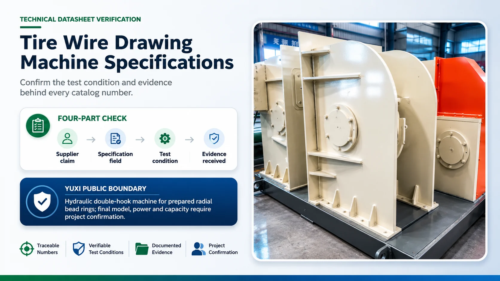
YUXI’s public tire wire drawing machine page provides the correct starting boundary: a hydraulic double-hook tire debeader for pulling bead steel wire from prepared radial tire rings before cutting, shredding, rubber-powder production or related pretreatment. It lists passenger-car, bus and truck tire rings as possible applications depending on size and configuration, and states that the exact model, motor power and capacity must be confirmed from tire diameter, bead construction and project layout.1
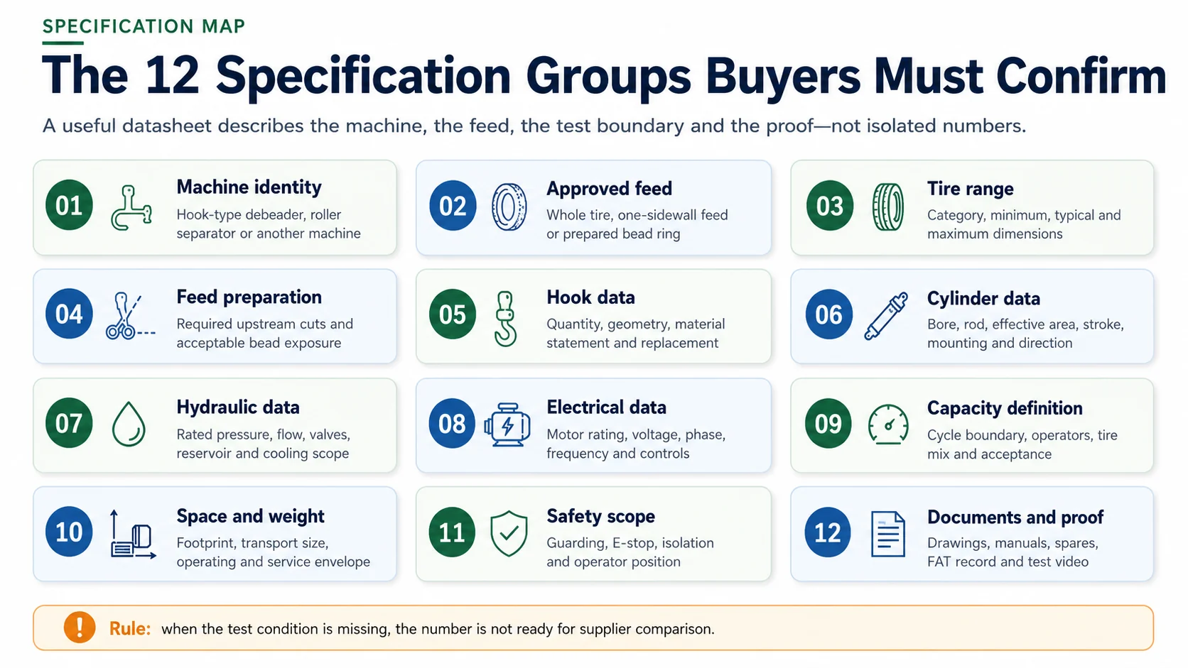
Before comparing tire wire drawing machine datasheets, confirm twelve specification groups: machine identity, approved feed, tire categories, minimum/typical/maximum workpiece dimensions, feed preparation, hook configuration, cylinder data, hydraulic data, motor and electrical supply, capacity definition, machine and installation space, safety controls and supporting documents.
For every field, require four pieces of information: the supplier’s stated value, the condition under which it applies, the evidence supplied and whether it is confirmed for your project. A blank field is safer than a precise-looking number with an undefined test.
The specification map separates machine identity, material range, hydraulic data, capacity, space, safety and proof.
1. Separate Specifications, Claims, Test Conditions and Evidence
A supplier sentence such as “high pulling force,” “suitable for truck tires” or “high capacity” is a claim. It may be directionally useful, but it is not yet a specification. A specification assigns a defined value or approved category to a named field. A test condition explains where that field applies. Evidence shows that the machine achieved it.
Layer
Example
Buyer question
Claim
“Heavy-duty hydraulic tire debeader.”
Heavy duty for which prepared tire category, dimensions and bead construction?
Specification
Approved feed, hook arrangement, cylinder stroke, electrical supply or completed rings per hour.
Is the field clearly defined and part of the final quotation?
Test condition
Prepared truck-tire bead rings, stated dimensions, one operator and a complete-cycle timing boundary.
Does this condition match the project feed and working method?
Evidence
Datasheet, drawing, calculation, component nameplate, continuous test video or signed FAT record.
Can the buyer trace the claim back to a document or representative test?
This four-layer method prevents an easy purchasing error: treating the strongest marketing phrase as the most important technical fact. The final machine specification should be traceable. A buyer should be able to point from each critical requirement to the relevant drawing, data sheet, manual section or test record.
2. Confirm the Machine Identity and Approved Feed First
“Tire wire drawing machine” is an industry label used for several different machines. A hook-type hydraulic debeader pulls a concentrated bead-wire bundle from prepared rubber. A roller or extrusion-style separator may press rubber away from bead wire. A sidewall wire remover may accept a different cut section. An OTR bead extractor can use a much larger frame, hook and loading arrangement.
The identity line should therefore state at least:
machine function and operating principle;
single-hook, double-hook or another extraction arrangement;
approved incoming material shape;
required upstream preparation;
approved tire categories;
normal loading direction and operator position;
the output condition the supplier considers a completed cycle.
Do not compare a prepared-ring hydraulic debeader with a whole-tire machine simply because both pages use the word “debeader.” If the physical input differs, the capacity, dimensions, power and labor figures describe different processes.
YUXI feed boundary: the public page describes prepared radial tire bead rings, especially rings with both sidewalls removed. A whole unprepared tire should not be assumed to be acceptable feed unless the final YUXI configuration and test record explicitly confirm it.
3. Approved Tire Categories and Workpiece Dimensions
A single “maximum tire diameter” is rarely enough. A flexible prepared ring interacts with the hook, support and frame through several dimensions. Two tire rings with the same outside diameter may have different widths, bead positions, wire bundle construction, residual sidewall rubber and weights.
The U.S. Tire Manufacturers Association notes that steel wire is used in tire beads and belts and may also be used in truck-tire plies. The bead wire anchors the tire to the wheel.2 That construction difference is one reason passenger, bus and truck tire inputs should not be reduced to diameter alone.
Dimension or category
What to state
Why the field matters
Tire category
Passenger, light truck, bus, truck, construction tire and any special tire class.
Separates materially different bead structures and handling loads.
Outside diameter
Minimum, typical and maximum prepared-ring outside diameter.
Checks loading path, restraint position, hook approach and frame clearance.
Ring width
Minimum, typical and maximum width after the stated preparation step.
Affects support, dual-hook alignment and machine envelope.
Bead-area dimensions
Accessible bead opening, residual rubber and any required exposed wire region.
Defines whether the hook can enter and capture the bundle.
Prepared-ring weight
Typical and maximum workpiece weight for each tire family.
Changes manual handling, lifting aids and sustainable cycle time.
Mix percentage
Expected share of each normal tire family per shift.
Supports weighted production testing rather than one best-case tire.
Keep OTR and mining tires as a separate engineered class. Do not extend a truck-tire specification to oversized tires by adding a larger diameter to the inquiry. Hook design, frame, cylinder, workpiece handling and safe operating area may all change.
4. State the Feed-Preparation Requirement
The datasheet should show the incoming material, not only name the original whole tire. Useful options include:
whole tire;
one sidewall removed;
both sidewalls removed;
separate bead-sidewall ring;
prepared bead ring with a defined rubber width;
another project-specific cut section.
This field changes hook access, ring stability, extraction stroke and cycle time. It also determines what upstream equipment and labor the plant needs before the debeader. A supplier capacity test using neatly prepared rings cannot be assigned to a project whose operators must perform extra cutting at the machine.
The feed-preparation drawing should include photos or a simple dimensioned sketch. Written phrases such as “waste tire” or “scrap radial tire” are not precise enough for FAT acceptance.
5. Confirm Hook Quantity, Geometry, Material Statement and Replacement
Hook quantity is only the first field. The specification should also describe the hook’s approach to the bead, engagement geometry, working movement, replaceable or fixed construction, material statement, heat-treatment evidence if claimed, inspection method and spare-hook scope.
For a double-hook machine, state whether the hooks move simultaneously, in a controlled sequence or through another arrangement. Also state how the system responds when one side engages before the other. Detailed configuration choice belongs to Single Hook vs Double Hook Tire Debeader; the specifications page should record the selected arrangement and its verified test condition rather than repeat the comparison.
Hook field
Minimum confirmation
Useful evidence
Quantity and sequence
One or two active hooks; simultaneous, sequential or supplier-defined movement.
Control description and continuous full-cycle video.
Geometry
Hook opening, approach path, working profile and approved bead access.
Dimensioned hook drawing or close equipment photographs.
Material claim
Material grade or approved material statement; heat treatment when claimed.
Supplier certificate or controlled part specification.
Replacement
Removal method, required tools, alignment check and service access.
Manual section and replacement demonstration.
Spare scope
Number of spare hooks, pins, bushings and related wear items included or recommended.
Itemized spare-parts list with part references.
6. Hydraulic Cylinder Specifications
A row labeled “hydraulic system” is not a cylinder specification. The cylinder converts fluid pressure into movement and theoretical force. Buyers should request the fields needed to understand the actual pulling direction and travel:
cylinder type and quantity;
bore diameter;
rod diameter;
effective piston area for the pulling side;
net working stroke;
pulling and return direction;
mounting arrangement;
approach, extraction and return times under the stated test condition;
hose and port arrangement;
seal and service information.
The rod diameter matters when the extraction movement uses the annular side of a double-acting cylinder, because the rod reduces effective area. The net working stroke matters because a high theoretical force is not useful if the hook cannot travel far enough to complete the approved extraction.
The working-principle article explains the complete force path in more detail: cylinder → hook assembly → bead bundle → tire restraint → machine frame. See How Does a Tire Wire Drawing Machine Work? for operation and process logic.
7. Hydraulic Pressure vs Theoretical and Usable Pulling Capability
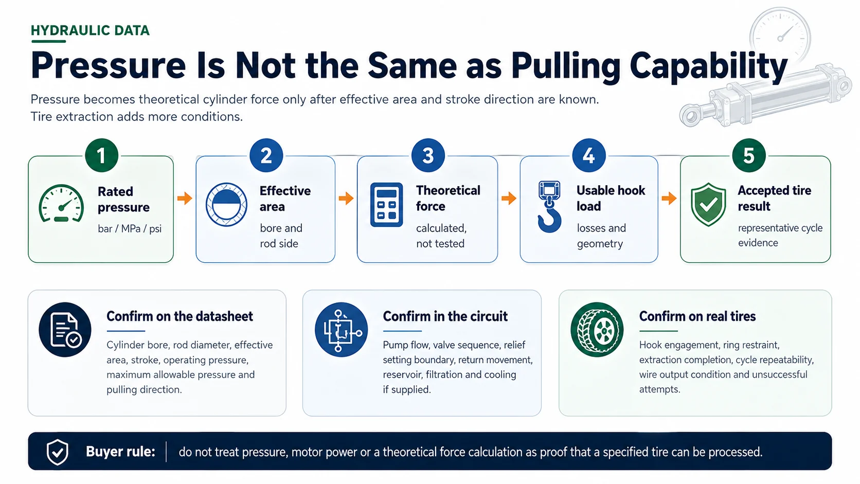
Hydraulic pressure is easy to publish because it is one number. It is not the same as pulling force, and neither number alone proves tire-processing capability.
Theoretical cylinder force = pressure at the cylinder × effective piston area
Parker’s hydraulic-cylinder technical documentation presents the same relationship and distinguishes push force from pull force because the piston rod reduces the effective area on the pull side.3 This relationship is a calculation boundary, not permission to change pressure settings or infer a YUXI force value.
Pressure and piston area provide a theoretical cylinder value; representative tire results require the complete force path.
The specification should distinguish:
Field
Meaning
Why it cannot stand alone
Rated operating pressure
The intended system or cylinder pressure under defined conditions.
Does not identify effective area, stroke or usable hook load.
Maximum allowable pressure
A design or component limit, not a normal target.
Operating at a limit is not evidence of proper machine selection.
Theoretical cylinder force
Pressure multiplied by effective area with the correct unit conversion.
Does not include friction, hydraulic losses, hook geometry or alignment.
Usable pulling capability
The force effectively transferred through the mechanism.
Still does not prove a tire will release cleanly.
Verified tire result
Completed extraction on a defined representative ring.
Applies only to the stated feed, test boundary and machine configuration.
8. Motor, Pump and Electrical Data
Motor power is not capacity. It is one part of the hydraulic power unit. A larger motor rating does not reveal the pump flow, pressure range, duty, cylinder area, valve sequence, hook engagement or time spent loading and clearing outputs.
The electrical and hydraulic-power-unit section should confirm:
motor rated power and duty information;
rated voltage, phase and frequency;
motor and control nameplate data;
pump type and rated flow at the relevant condition;
reservoir arrangement and nominal oil volume where approved for publication;
filtration and cooling equipment included in the quotation;
starting method or variable-speed drive if supplied;
control voltage and enclosure information;
electrical schematic and terminal requirements;
site power assumptions and allowable configuration options.
U.S. Department of Energy motor guidance treats rated voltage, frequency and power as defined motor operating data, not as a production-throughput measure.4 For a tire debeader, those fields establish utility compatibility and drive-system scope. They do not replace a full-cycle tire test.
9. Define Tire Debeader Capacity Before Comparing It
A catalog can express “capacity” as pulls per hour, bead sides per hour, tires per hour, rings per hour, tons per hour or output per shift. Those units are not interchangeable. A double-hook cycle can remove two bead areas in one setup, while another machine may count each side as one operation.
A defensible capacity statement should include:
machine identity and hook configuration;
feed state and upstream preparation;
tire category and size test set;
number of operators and lifting aids;
cycle start and stop points;
whether both bead sides are completed;
accepted output condition;
how failed engagement and correction are recorded;
number of consecutive test cycles;
productive minutes used for shift output;
normal tire-mix percentages.
Capacity term
What it measures
Suitable use
Active pull time
Only the extraction stroke.
Component motion comparison; not plant output.
Machine movement time
Approach, pull, return and controlled reset.
Hydraulic and control sequence review.
Full completed-ring cycle
Loading through both outputs cleared and ready for the next ring.
Machine and labor comparison.
Sustainable hourly output
Accepted rings across productive time with normal variation.
Line balancing and shift planning.
Mixed-stream shift output
Weighted result for the normal percentage of each tire family.
Project acceptance and staffing.
The broader buying guide explains how capacity affects model selection and labor. See How to Choose a Tire Debeader Machine. This specifications article owns the definitions and evidence fields, not the complete selection process.
10. Machine Dimensions Are Not the Installation Envelope
Supplier dimensions often describe the machine’s main frame or transport condition. The operating cell needs more space. A buyer should request at least four separate drawings or dimension groups:
transport dimensions and lifting points;
installed machine footprint and overall height;
operating envelope for the hook and moving components;
loading, wire discharge, rubber discharge and maintenance clearances.
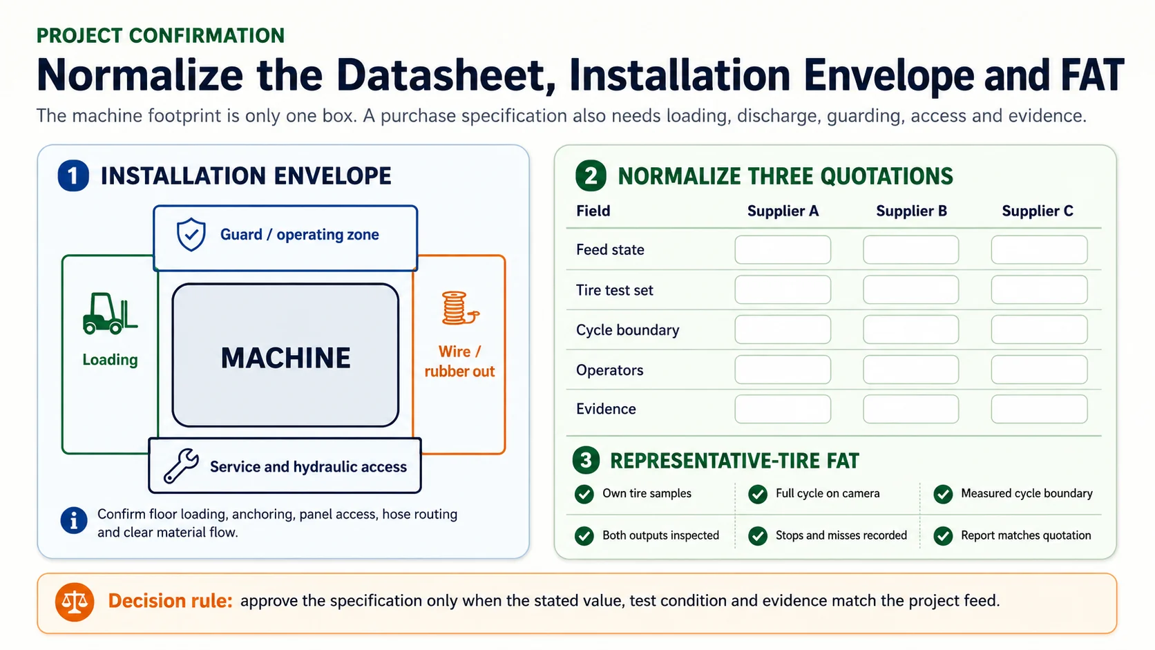
Normalize the physical cell and test conditions, not only the machine frame dimensions.
Space field
What to include
Typical omission to catch
Loading area
Incoming-ring staging, operator path, lift aid and maximum workpiece swing.
The machine fits, but the largest ring cannot be safely oriented.
Wire discharge
Direction, containment, collection bin and clearing route.
Extracted spring-like wire blocks the next load.
Rubber discharge
Remaining ring destination, conveyor or manual route.
Rubber and wire flows cross each other.
Guarding envelope
Doors, fixed guards, interlocks and safe operating position.
Guard opening is not shown on the floor plan.
Service clearance
Hydraulic station, panel doors, cylinder, hooks, hoses and replacement work.
Routine service requires moving another machine.
Foundation and anchoring
Machine weight, operating loads, support and approved anchoring plan.
Only shipping weight is supplied.
11. Controls, Guarding, Isolation and Operator Position
A specifications sheet should not use “safe operation” as a substitute for a described safety scope. OSHA’s general machine-guarding rule requires methods that protect operators and other employees from point-of-operation and moving-part hazards.5 OSHA’s control-of-hazardous-energy standard covers servicing and maintenance in which unexpected start-up or stored-energy release could cause injury.6
For a hydraulic hook-type debeader, buyers should ask the supplier to state:
normal operator location and approved loading method;
fixed and movable guard arrangement;
emergency-stop locations;
start, stop, reset and restart behavior;
interlocks or presence-sensing devices if supplied;
electrical disconnect and hydraulic isolation points;
stored-pressure release and verification method;
safe procedure for wire clearing, hook inspection and maintenance;
warning labels, manuals and training materials included;
which local compliance work remains the buyer’s responsibility.
The final safety design must be reviewed against the delivered machine, installation and applicable local requirements. A website article cannot certify compliance for a particular plant or replace the supplier’s risk assessment and manual.
12. Define Output Condition and Downstream Compatibility
A completed cycle creates an extracted bead-wire bundle and a rubber-rich ring. The specification should state how much residual rubber on the bead wire is acceptable, whether broken or partially extracted bundles are accepted, and what condition the remaining ring must have for the next machine.
A tire debeader does not remove all steel from the tire. USTMA’s construction overview distinguishes bead wire from steel belts and truck-tire steel plies.2 The downstream line may still require shredding, liberation and magnetic separation.
Record the next machine and its input requirement:
tire cutter and required ring shape;
tire shredder feed opening and loading method;
rubber crusher or granulation input size;
rubber-powder line pretreatment condition;
pyrolysis preparation and required size reduction;
wire collection, storage and scrap handling.
The debeader’s sustainable rate should fit the receiving equipment and buffer. A higher isolated machine figure is not an advantage when it creates uncontrolled piles, cross-traffic or frequent stopping.
13. Documentation, Spare Parts and Service Data
Documents turn a specification into something the buyer can install, inspect and maintain. At minimum, confirm which revision of each document is included and whether the final set matches the shipped configuration.
Document or data item
Purpose
Confirmation point
Technical datasheet
Records the approved model and main project parameters.
Signed or referenced in the quotation and order.
General arrangement drawing
Shows dimensions, loading, outputs, access and utilities.
Matches final guards, panel and hydraulic station.
Hydraulic schematic
Shows pump, valves, cylinder, pressure-control and isolation arrangement.
Revision matches delivered components.
Electrical drawing
Shows supply, controls, protection and terminal information.
Matches site voltage and delivered panel.
Operating and safety manual
Defines approved feed, cycle, controls, inspection and restrictions.
Available in the agreed language and configuration.
Maintenance information
Provides approved inspection, lubrication and service tasks.
No universal interval is invented outside the manual.
Spare-parts list
Identifies hooks, pins, bushings, seals, hoses and electrical items.
Part references and included quantities are clear.
FAT record
Connects the stated specification to the representative-tire test.
Includes tire data, cycle boundary, results and deviations.
Commercial price, delivery terms, packing, commissioning and landed-cost exclusions belong to the Tire Debeader Machine Price & RFQ Guide. This article keeps documentation discussion limited to technical specification and verification.
14. How to Normalize Three Supplier Datasheets
Create one buyer-controlled comparison sheet. Do not preserve each supplier’s preferred row names when they hide different definitions. Rewrite all three quotations into the same fields and mark unknown conditions as “not stated.”
Normalization field
Supplier A
Supplier B
Supplier C
Buyer decision
Machine identity
Stated value
Stated value
Stated value
Are the operating principles comparable?
Approved feed state
Stated / not stated
Stated / not stated
Stated / not stated
Use one project feed definition.
Tire test set
Category and dimensions
Category and dimensions
Category and dimensions
Require the same representative range.
Hook sequence
Single / simultaneous / sequential / unclear
…
…
Confirm the delivered control logic.
Hydraulic calculation
Pressure, area and direction
…
…
Separate calculated force from tire proof.
Capacity boundary
Cycle start/stop, operator count and accepted output
…
…
Reject undefined comparison figures.
Installation envelope
Machine plus loading, discharge and service areas
…
…
Compare the complete work cell.
Evidence supplied
Drawing, video, report, manual or none
…
…
Assign confidence by evidence quality.
A supplier with a lower catalog number may have given a more conservative full-cycle result. A supplier with the largest pressure or power may have tested a smaller or more prepared ring. Normalization makes those hidden differences visible.
15. Specifications YUXI Must Confirm by Project
The current public YUXI product information supports several qualitative facts: hydraulic double-hook architecture, high-strength hooks, manual loading with hydraulic pulling, prepared radial bead-ring feed and possible passenger-car, bus and truck applications depending on configuration. It also places the machine before cutting, shredding, rubber-powder production and related pretreatment.
The public page does not provide enough approved detail to publish one universal numerical specification. The following fields should therefore remain in the formal project-confirmation table:
Project-confirmation field
Buyer input
YUXI output
Approved feed and tire range
Photos, preparation video, categories, dimensions, weights and mix percentages.
Confirmed material boundary and required upstream preparation.
Hook arrangement
Required bead sides, handling workflow and representative difficult ring.
Final hook quantity, geometry, sequence and spare scope.
Cylinder and hydraulics
Required workpiece range and test acceptance.
Bore, rod, stroke, direction, operating data and hydraulic-station configuration.
Motor and electrical supply
Country, site voltage, phase, frequency and panel requirements.
Motor, pump and control data matched to the supply.
Capacity
Completed acceptable rings per hour or shift, tire mix and productive time.
Defined full-cycle test target and project-specific expected output.
Machine and installation dimensions
Workshop drawing, access, material flow and lifting plan.
General arrangement, operating envelope, weight and foundation information.
Safety and documentation
Local standards, plant requirements and operating language.
Delivered guarding, controls, manuals, drawings and remaining site responsibilities.
FAT evidence
Representative tire samples and agreed test protocol.
Continuous video, measurements, output inspection and signed results.
16. Representative-Tire FAT Checklist
A factory acceptance test should verify the high-risk specifications, not merely show that the unloaded machine moves. Agree on the test protocol before the buyer ships samples or the supplier selects local tires.
Identify every test ring by original tire category, preparation method and dimensions.
Include a common ring and the largest difficult normal ring from the project.
Confirm that the tested machine matches the quoted hook, hydraulic, control and guarding configuration.
Show the complete cycle in one camera sequence: load, position, engage, pull, release, clear outputs and reset.
State whether both bead sides must be completed and how partial extraction is classified.
Record the number of operators and every lifting or positioning aid.
Use the agreed capacity start and stop points.
Record failed engagement, correction, stops and abnormal wire release instead of editing them out.
Inspect the extracted wire bundle and remaining rubber-rich ring.
Check machine movement, leakage, unusual sound and control response without instructing unsafe proximity.
Verify emergency controls and isolation documentation using the approved test method.
Issue a report that references the final quotation and records deviations or retest actions.
Request a Verified YUXI Technical Datasheet
Send the prepared tire photos and video, minimum/typical/maximum dimensions, tire-mix percentages, target completed rings per shift, site electrical supply, workshop layout and downstream process. Ask YUXI to return the project-specific datasheet, general arrangement and representative-tire FAT plan.
Comparing machines before confirming the feed state
A capacity figure for a prepared ring cannot be assigned to a whole-tire process that includes additional cutting and handling.
Treating maximum tire diameter as the complete material range
Ring width, weight, bead access, residual rubber and construction can change hook engagement even at the same outside diameter.
Using hydraulic pressure as the pulling-force specification
Pressure requires effective area and pulling direction to produce a theoretical cylinder value. Actual extraction requires the complete machine and tire test.
Using motor power as a capacity ranking
Power does not reveal pump flow, cylinder geometry, full-cycle handling, first-pass acceptance or downstream waiting.
Publishing the fastest isolated cycle
The production figure should include normal consecutive cycles, output clearing, corrections, tire variation and productive shift time.
Using machine footprint as the required workshop space
The work cell needs loading, guard, discharge, panel, hydraulic and service access.
Accepting “all tires” as an approved range
Passenger, bus, truck, construction and OTR applications need defined dimensions and representative proof. OTR should remain a separate engineered class.
Receiving documents that do not match the shipped revision
The datasheet, drawing, schematic, manual and spare-parts list should reference the final configuration and revision.
Frequently Asked Questions
Which tire wire drawing machine specification should be confirmed first?
Confirm the machine identity and approved feed state first. A hook-type tire debeader for prepared bead rings cannot be compared directly with a roller separator, sidewall wire remover or OTR bead extractor, even when the product names look similar.
Is a higher hydraulic pressure always better?
No. Theoretical cylinder force depends on pressure and effective piston area, while useful tire extraction also depends on stroke direction, hook geometry, ring restraint, frame alignment, hydraulic losses and the actual bead structure. Higher pressure is not a substitute for representative-tire evidence.
Does motor power tell me the capacity of a tire debeader?
No. Motor power is one electrical and hydraulic-system input. Capacity depends on the complete cycle: loading, positioning, hook engagement, pulling, release, output clearing, reset, tire mix, first-pass acceptance and available productive time.
What dimensions should a supplier state?
Request minimum, typical and maximum prepared-ring outside diameter, ring width, bead-area dimensions and approximate workpiece weight. Also request transport dimensions, operating footprint, loading clearance, discharge area and maintenance access.
What does YUXI need to confirm for the final specification?
YUXI publicly states that the exact model, motor power and capacity depend on tire diameter, bead construction and project layout. The final technical datasheet should also confirm feed preparation, hook configuration, cylinder and hydraulic data, electrical supply, full-cycle capacity boundary, machine dimensions, guarding, documents and test evidence.
How should I compare three supplier datasheets?
Put every supplier into one comparison sheet using the same machine type, feed state, tire test set, cycle start and stop points, operator count, accepted output definition and evidence requirement. Leave a field unconfirmed when the supplier has not stated the test condition.
References and Source Notes
U.S. Tire Manufacturers Association, “Tires 101,” tire steel, bead and belt construction overview. Source
Parker Hannifin, “Metric Hydraulic Cylinders, Series HMI,” theoretical push and pull force calculation using pressure and effective piston area. Source
U.S. Department of Energy, “Premium Efficiency Motor Selection and Application Guide,” rated motor voltage, frequency, power and operating data. Source
U.S. Occupational Safety and Health Administration, 29 CFR 1910.212, General Requirements for All Machines. Source
U.S. Occupational Safety and Health Administration, 29 CFR 1910.147, Control of Hazardous Energy. Source
Marie has 8+ years of experience in tire shredding and recycling equipment,with a focus on tire shredders,rubber recycling machines,TDF production,rubber crumb processing,and complete tire recycling systems.