




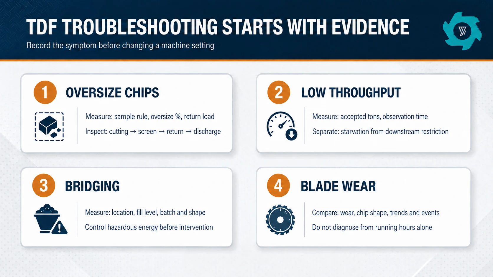
A TDF line can look busy and still lose saleable output. The shredder turns, conveyors move and chips appear at discharge, yet the oversize pile grows, the feed hopper repeatedly empties, or the operator has to reverse the chamber more often. Troubleshooting starts by separating those symptoms. “The plant is slow” is not a diagnosis.
The practical method is to freeze the production boundary, record what changed, and follow the material from receiving to accepted TDF. This guide focuses on four recurring operating problems: oversize chips, low finished throughput, bridging and accelerated blade wear.
Start With Evidence, Not the First Visible Problem
Before adjusting a screen, changing blades or increasing feed, establish a short baseline. Use a representative production window and record incoming tire mix, actual feed mass, accepted finished mass, oversize or return mass, reversals, idle gaps, alarms and stoppage reasons. If the tire mix changed from mostly passenger tires to a heavier truck-tire stream, compare like with like.
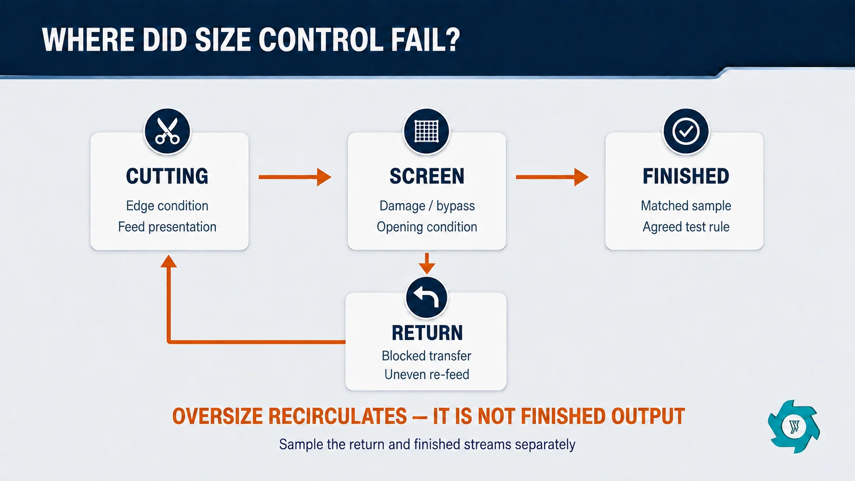
The current YUXI Tire TDF Plant uses screening and oversize return to control chip size. That matters diagnostically: a problem seen at finished discharge may have started in feeding, cutting, screening or the return path.
| Observed symptom | Measure first | Do not assume |
|---|---|---|
| More oversize in finished TDF | Sampling method, oversize percentage, screen and return status | The screen opening alone defines every chip |
| Lower accepted tons per hour | Feed mass, return load, productive minutes and accepted output | The shredder motor is automatically the bottleneck |
| Hopper or chute bridging | Where flow stops, material shape, fill level and feed pattern | More loader pressure will cure the geometry |
| Faster apparent blade wear | Wear pattern, tire mix, foreign-object events and cutting behavior | Operating hours alone explain blade condition |
Oversize Chips: Find Where Size Control Was Lost
Tire chips are flexible and irregular. A long narrow strip, folded piece and bulky chunk may behave differently in a screen and during manual measurement. Use the receiver’s written test method, sampling point and tolerance. This avoids treating a sampling change as a machine fault.
1. Check the finished stream and return stream separately
Take matched samples from finished discharge and from the oversize return path. If return load is high but finished oversize remains controlled, the loop may be doing its job while consuming capacity. If obvious oversize reaches finished discharge, inspect bypasses, screen damage, loose panels, worn openings and unintended paths around the sizing device.
2. Inspect cutting evidence
Look for a change in chip shape: more long strips, partially torn sections, repeated folds or pieces that show crushing without a clean cut. These clues can point toward dull cutting edges, clearance or alignment issues, loose holders, an unsuitable feed presentation, or a chamber that is being flooded faster than it can make effective cuts.
3. Verify the return loop
A stopped or intermittently blocked return conveyor may overflow, spill, build a false backlog or allow material to take an unintended route. Confirm direction, belt or chain movement, transfer-point clearance, sensor operation and whether returned chips are reintroduced evenly. Do not increase fresh feed until the internal circulating load is understood.
For the commercial limits that define an accepted lot, use the separate TDF quality specification guide. The troubleshooting question is narrower: which stage stopped holding the agreed limit?
Low Throughput: Measure Accepted Output and Productive Time
Count accepted finished TDF tons over the defined observation period, then use the same time boundary for every comparison. Raw tires loaded, shredder discharge and accepted material are not interchangeable.
Separate starvation from restriction
A starved chamber has idle gaps because material is not arriving consistently. Causes may include loader timing, an undersized or poorly controlled feed conveyor, bridging, slow pre-cutting or operator hesitation after reversals. A restricted line receives material but cannot move it through screening, return or discharge fast enough. That condition may show as rising return inventory, frequent stops, conveyor overload or a chamber that repeatedly reverses under a heavy bed of material.
Build a simple loss tree
Split scheduled production time into productive running, planned stops, unplanned stops and running-but-not-producing periods. Then give every lost interval one primary reason. Five minutes waiting for feed is not blade-change time. A return conveyor trip should not be recorded as “shredder slow.” Clear reason codes prevent the team from replacing wear parts to solve a material-handling problem.
- Compare actual feed mix with the baseline.
- Check fresh-feed rate and gaps between loads.
- Record reversal frequency and duration.
- Measure or estimate return load consistently.
- Confirm screen, discharge conveyor and storage availability.
- Compare accepted output over the same observation window.
Bridging: Locate the Geometry and the Trigger
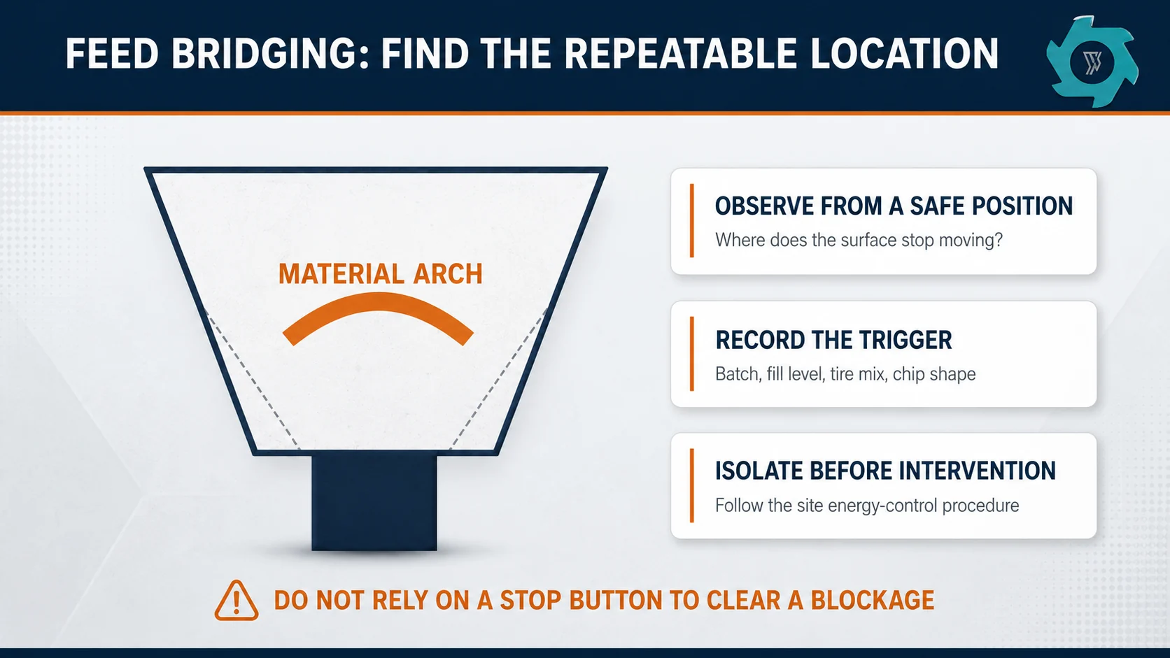
Bridging occurs when tires or chips form a stable arch across a hopper, chute or transfer. The equipment below the bridge may be ready to run while little material reaches it. Elastic sidewalls, long strips, exposed wire, mixed piece shapes and an overfilled hopper can interlock. A narrow transition, shallow wall angle or protruding edge can give the arch a place to form.
Observe before clearing
From a safe position, note where the material surface stops moving. Record hopper level, feed batch size, tire type, moisture condition, chip shape and the position of the last successful transfer. Video from a protected external viewpoint can reveal whether the bridge begins after a large batch, during low hopper level, or when long returned pieces arrive together.
Do not turn blockage clearing into routine improvisation
Reaching into, entering or servicing jammed equipment can expose workers to unexpected startup and stored mechanical, electrical, hydraulic or pneumatic energy. OSHA’s hazardous-energy-control standard covers servicing and maintenance where unexpected energization, startup or release of stored energy could cause injury.1 Follow the site-specific procedure, isolate relevant energy sources, verify the safe state and use authorized personnel.
After safe inspection, look for polished contact points, caught wire, damaged liners, loose guards, ledges, narrowing transitions and material that repeatedly hangs in the same location. Corrective action may involve feed sequencing, batch size, material preparation, transfer geometry or equipment condition. Any structural change should be reviewed by the equipment supplier or a qualified engineer.
Blade Wear: Confirm the Pattern Before Replacing Parts
Blade wear can reduce bite, lengthen cutting time and produce more pulling or folding. But low throughput by itself does not prove that the blades are worn. The same symptom can come from poor feeding, excessive return load, changed tire construction, screen restriction or downstream trips.
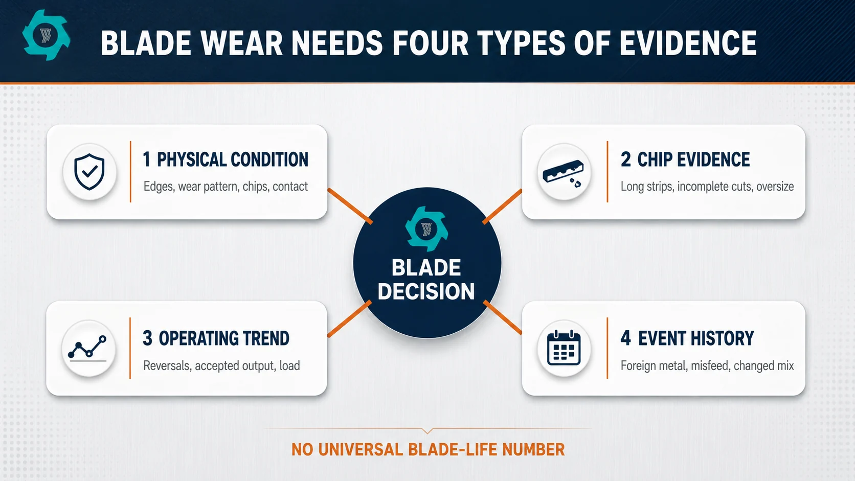
Compare four kinds of evidence
- Visual condition: rounded edges, uneven wear, chipping, cracking, abnormal contact marks or material packed around holders.
- Product evidence: more long strips, incomplete cuts or a rising oversize trend under a comparable feed mix.
- Operating trend: more reversals, longer residence, falling accepted output or a change in current/load signature where properly instrumented.
- Event history: foreign metal, rims, oversized unprepared tires, abnormal impacts, misfeeds or recent reassembly.
Heavy bead sections can add cutting load. Whether bead wire should be removed depends on the tire range, machine design and final-product requirement; the separate guide on removing tire beads before shredding explains that project decision. During troubleshooting, verify whether the incoming preparation practice changed.
Do not publish or adopt a universal blade-life number. Replacement or sharpening decisions should follow the supplier’s allowable geometry, service limits and inspection evidence. Unapproved grinding can change fit, clearance or strength. After blade work, verify fasteners, alignment, guards, rotation and no-load checks according to the manual before a controlled production test.
A Controlled Recovery Test
Once the likely cause is corrected, run a defined recovery test. State the tire mix, preparation condition, screen configuration, feed method, observation time and acceptance rule before starting. Record fresh feed, accepted output, return load, oversize result, reversals, alarms and stoppage reasons. Compare the result with the baseline, not with an unrelated best-ever shift.
The YUXI tire shredder machine is described with a dual-shaft cutting chamber and disc-screen return system. For a plant-specific review, send YUXI the machine configuration, tire photos, maximum dimensions, feed mix, target chip rule, recent samples, alarm history, maintenance record and short operating videos captured from safe positions.
- the symptom has a measurable definition;
- the cause is supported by inspection or trend evidence;
- the corrective action is documented;
- the recovery test uses the same measurement boundary;
- accepted output and quality return to the agreed range.
Frequently Asked Questions
Why is a TDF plant producing too many oversize chips?
First confirm the sampling and size rule. Then inspect the screen, return conveyor, cutting condition, feed rate and tire mix. A worn or damaged screen, ineffective cutting, an overloaded chamber or a return-path fault can all increase oversize discharge.
Why does TDF throughput fall even when the shredder is running?
Running time is not the same as accepted output. Check actual feed mass, return load, idle gaps, reversals, conveyor availability, screen condition and accepted finished tons over the same period.
How should feed bridging be cleared safely?
Stop feeding and follow the site-specific hazardous-energy-control procedure before entering, reaching into or servicing the affected equipment. Do not rely on the stop button alone. Identify and isolate all relevant energy sources before clearing or inspecting the blockage.
Does low throughput always mean the blades are worn?
No. Blade wear is one possible cause, but unstable feeding, a high return ratio, changed tire mix, screen problems, conveyor restrictions and control trips can create the same symptom. Compare wear evidence with operating trends before replacing parts.
How can operators confirm that a troubleshooting change worked?
Change one controlled variable where practical, run a defined observation window, and compare accepted output, oversize rate, return load, reversals and stoppage reasons with the baseline under a similar tire mix.
Need Help Diagnosing a TDF Line?
Send your tire mix, target chip rule, actual output data, oversize samples, alarm history and operating videos. YUXI can review the evidence against the line configuration.
Engineering References
- OSHA, lockout standard: hazardous-energy control for maintenance.