




This is a practical factory-planning guide, which aims at turning a rubber-powder equipment list into a workshop that can be installed, operated, expanded, maintained and cleaned.
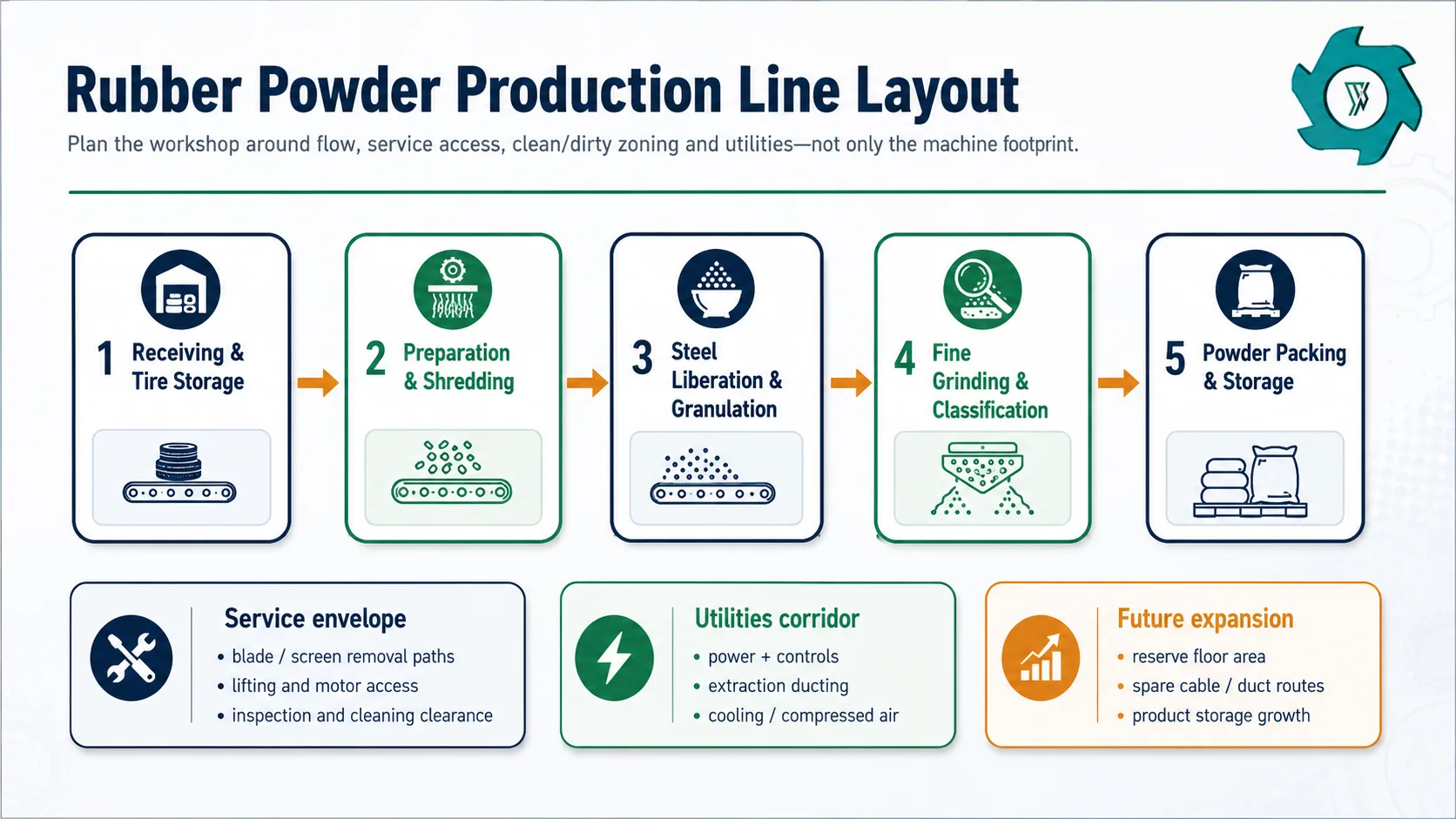
A rubber powder production line should not be laid out as a row of machines with whatever space is left between them. The final grinding section adds fine material handling, classification, dust extraction, cooling and packaging duties that are easy to underestimate. A line can fit inside the workshop on paper and still be difficult to run if the forklift route cuts through the operator area, a screen cannot be removed, a dust duct blocks a service platform, or the electrical room has no practical cable route.
Define the process boundary before you calculate the building footprint or electrical load. A project that starts with whole passenger and truck tires needs receiving, tire preparation, primary shredding, steel liberation and much more heavy material handling than a project that starts with clean 1–8 mm rubber granulate. Both may be called a “rubber powder line,” but their site requirements are not remotely the same.
What Must a Rubber Powder Plant Layout Include?
A workable rubber powder plant layout includes more than the machine footprint. Reserve space for material flow, machine service envelopes, forklift and pedestrian routes, raw tire and finished-powder storage, steel and fiber by-products, electrical equipment, dust extraction, cooling, compressed air where required, packaging, maintenance work and future expansion. Build the electrical requirement from the actual motor and auxiliary list. Final dimensions should be tied to the selected equipment and the real building rather than a generic square-metre-per-ton rule.
The reason this matters is that powder production adds several “invisible” systems around the mechanical line. A grinder needs a controlled feed. Classification can create a return loop. Fine product needs enclosed collection and packaging. Dust extraction needs pickup points, ducts, filters and inspection access. Cooling may need piping, a heat-rejection point and service clearance. None of these items disappears because the machine supplier’s preliminary brochure only shows the main equipment.
EPA describes tire crumb production as staged reduction with screens, magnets and air separation, including return of oversize material to the reduction process.[1] Fine rubber powder extends that logic downstream. Once a clean granulate is ground to a smaller particle size, classification, return load and fine-material handling become a larger part of the plant design.
Fix the Project Boundary Before Fixing the Footprint
“How much space does a 2 T/H rubber powder line need?” sounds like a clean question, but the capacity number does not define the scope. The same nominal powder output can start from three very different feed conditions.
| Starting point | What the site must usually accommodate | Layout consequence |
|---|---|---|
| Whole tires | Receiving, sorting, possible bead/tire preparation, shredding, screening/return, steel liberation, granulation, fiber removal, fine grinding and packing | Largest handling and storage footprint; more heavy-duty access and more by-product movement |
| Wire-free chips | Controlled feeding, further granulation, magnetic cleanup, fiber separation, grading, fine grinding and product collection | Smaller front end, but the finishing section still needs real utility and service space |
| Clean 1–8 mm granulate | Metered feed, final grinding, classification/return, cooling, dust collection and packing | Most compact process boundary, but often the highest concentration of fine-dust and cooling duties |
This distinction also prevents duplicate content planning. A crumb rubber plant layout can stop after granulation, grading and cleaning. A powder plant continues into finer grinding and classification, so it needs extra downstream equipment, extra collection points and usually a more deliberate utility layout.
Divide the Workshop Into Functional Zones
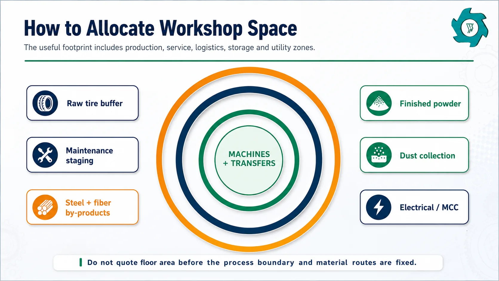
1. Raw tire receiving and buffer storage
If the project begins with whole tires, receiving can use more site area than the machines themselves. Trucks need a route, tires need a controlled place to wait, and sorting should happen before the production feed point. The final storage arrangement also depends on local fire, environmental and waste-tire rules, so the equipment supplier’s drawing should not be treated as the permit drawing.
2. Dirty front-end processing
Tire cutting, shredding and initial steel liberation handle bulky, irregular and comparatively dirty material. Keep this area close to receiving so large tires and rough shreds do not travel through the clean-product side of the building. Heavy maintenance work also tends to happen here, so crane, forklift or hoist access should be considered early.
3. Granulation and separation
This middle zone turns the coarse rubber/steel mix into a more controlled granulate. It normally includes screens, magnets, fiber separation and return conveyors. Crossovers become a common problem here because several streams leave the main line at once.
4. Fine grinding and classification
The grinder, screen or classifier, return circuit, collection system and cooling arrangement need to be treated as one operating cell. A narrow space around the mill may look efficient on the drawing but becomes expensive when wear parts or screens need to be changed.
5. Powder packing and finished-goods storage
Finished rubber powder is not the end of the line until it is packed, labeled, moved and stored. Bagging rate must match the accepted powder rate, not the upstream shredder rate. Leave room for pallets or bulk bags, scales, sampling, rejected/hold product and forklift pickup without pushing forklifts back through the fine-grinding service zone.
6. Steel, fiber and reject handling
Recovered steel and textile are separate logistics streams. Their bins should be reachable without crossing the clean powder packing route. A plant that produces good rubber powder can still lose time every shift if a steel bin blocks the only maintenance aisle or fiber collection needs constant manual rehandling.
Material Flow, Forklift Routes and Clean/Dirty Separation
For most new workshops, a mostly one-direction material flow is easiest to understand. Raw tires enter one side; progressively cleaner rubber moves toward the powder side; steel, fiber and rejects branch away; finished powder leaves without going back through receiving.
OSHA’s general material-handling rule requires sufficient safe clearances where mechanical handling equipment is used and requires aisles and passageways to be kept clear and appropriately marked.[2] That does not provide one universal aisle width for a tire plant, but it is a good reminder that forklift movement is part of the design, not leftover space.
Clean/dirty zoning is also practical quality control. Fine powder can be re-contaminated by loose steel, textile or dust from the front end if bins, forklifts and housekeeping tools move freely between zones. A simple physical and operating separation often does more for product consistency than adding another separator at the end.
Maintenance Clearance and Clear Height Matter as Much as Floor Area
A machine footprint normally shows the frame, motor and guards. It may not show the envelope needed to remove a rotor, shaft, screen, bearing, pulley, knife set or grinding component. Service clearance should be drawn around the machine as a real zone.
Clear height can be just as limiting. Conveyors rise; magnetic separators need discharge space; air ducts need routing; platforms need headroom; bag filters need service clearance; and lifting equipment needs hook height. An existing building with plenty of floor area can still be unsuitable because beams, cranes or roof services force awkward conveyor and duct geometry.
Power Planning Starts With a Load List, Not One kW Number
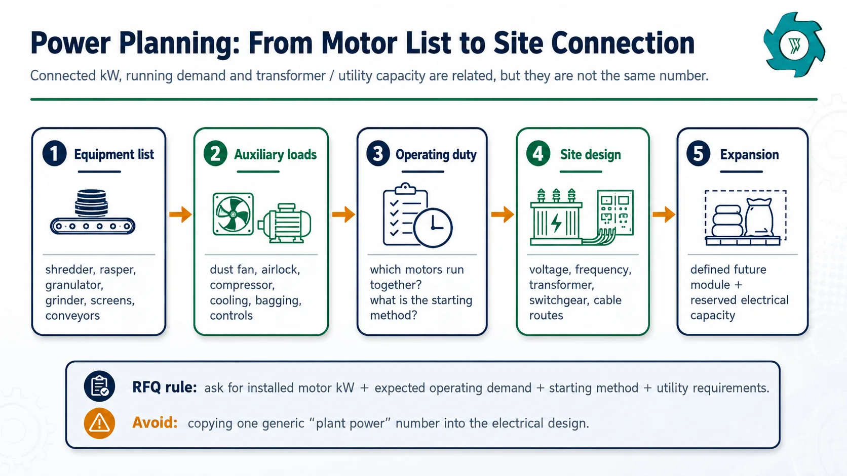
Build the connected-load list machine by machine
Include every driven item inside the project scope: shredder, rasper, granulator, powder grinder, screens, conveyors, magnetic separators, air-separation fans, classifier, dust collector fan, rotary valves, cooling pumps, compressors, bagging equipment and control auxiliaries. If a device is supplied locally rather than by the line manufacturer, keep it on the site load list anyway.
The rubber powder plant capacity guide explains why the finishing section can become the bottleneck as output rises or mesh becomes finer. The same point applies electrically: a larger upstream shredder does not tell you the demand of the fine-grinding circuit.
Then define which loads run together
A connected-load total assumes every nameplate is added. Actual running demand depends on operating sequence and load factor. The final electrical engineer also needs to know which large motors start while others are running, the proposed starting method, voltage and frequency, local short-circuit conditions, permitted voltage drop and any utility restrictions.
Leave expansion capacity for a defined reason
“Add 30% spare” sounds safe, but it is not a design basis by itself. If the business plan includes a second powder grinder, automatic bagging or another classifier, reserve capacity for those named loads and reserve the physical cable, switchgear and floor-space routes too. If no future load is defined, a random margin can waste money without solving the actual expansion problem.
Utilities: Dust, Cooling, Compressed Air and Product Handling
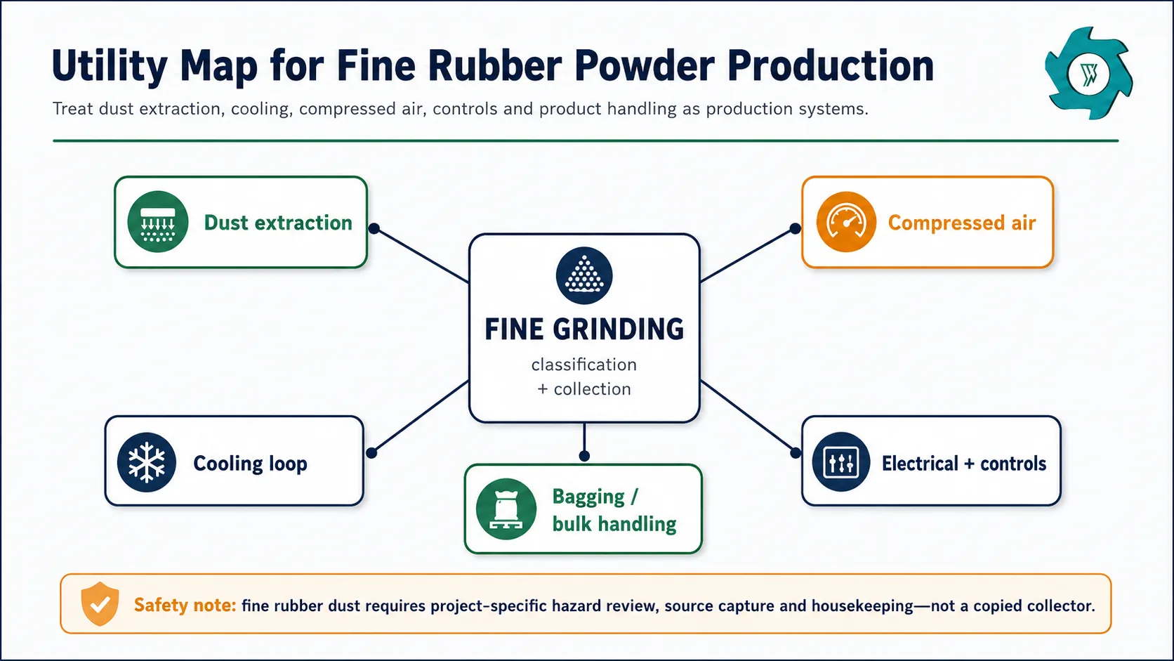
Dust extraction
Fine rubber handling deserves a dedicated hazard review. OSHA’s combustible-dust National Emphasis Program explicitly includes tire and rubber manufacturing among industries where combustible dust hazards may exist, and its background material cites a fatal rubber-dust explosion at a rubber fabricating plant.[3] That does not mean every rubber-powder line has the same hazard level or needs the same collector configuration. It means the project should not treat dust control as a cosmetic housekeeping accessory.
Capture points commonly appear around fine grinding, screens/classifiers, transfers, fiber separation and powder collection. Duct routing should be shown on the plant drawing while the equipment elevations are still flexible. Collector service access, filter replacement, discharge handling, cleanout points and the final location relative to the building all need project-specific review.
Cooling
Ambient fine grinding turns mechanical work into heat. As particle size decreases, temperature control can affect throughput, material behavior and equipment wear. The exact cooling method depends on the selected grinder and supplier design, but the layout should reserve the required pumps, piping, heat exchanger or cooling-tower interfaces instead of discovering them after the line has been installed.
Compressed air
Compressed air may be required for pulse-jet filter cleaning, actuators or packaging equipment. Do not assume it is negligible. The quotation should state required pressure, flow and air quality, whether the compressor is included, and whether the demand is continuous or intermittent. A plant that already has a compressor should still check that its available capacity reaches the new line at acceptable pressure.
Ventilation, fire protection and housekeeping
General ventilation, local extraction and fire-protection interfaces should be separated in the project documents. One system does not automatically replace another. Local codes, insurer requirements and the project dust-hazard assessment determine the final arrangement. Housekeeping access should also be built into the layout—especially under conveyors, around powder collection and near duct pickup points—because inaccessible floors quickly become neglected floors.
Capacity and Mesh Change the Layout More Than Buyers Expect
A 1 T/H and a 5 T/H powder plant are not simply scaled copies. Larger capacity increases receiving, buffer storage, packaging and by-product movement. Finer mesh increases grinding, classification, cooling and dust-handling duty. Those two effects can pull the layout in different directions.
| Design change | What grows first | Typical layout consequence |
|---|---|---|
| Higher whole-tire input | Receiving, shredding, steel handling, buffers | More yard/truck movement and larger dirty-zone logistics |
| Higher accepted powder T/H | Fine grinding, classification, collection, packing | Parallel finishing equipment or wider service/utility zones may become attractive |
| Finer mesh target | Grinding work, return load, heat removal, fine dust capture | More attention to grinder cells, classifier loops, cooling and extraction |
| More product grades | Screens, bins, valves, packaging and storage | More branches after the finishing section; greater risk of cross-traffic |
| Longer operating hours | Maintenance organization, spares, staffing, storage turnover | Access and maintainability become more valuable than minimum footprint |
The site’s rubber powder machine selection guide takes the same approach from the equipment side: define target mesh, accepted capacity, feed condition and contamination limits before comparing machine size. Those inputs should also be written on the layout drawing because they explain why a particular grinding and utility arrangement exists.
When several powder grades will be sold, consider how changeover and sampling happen. Extra bins can simplify production, but only if operators can reach them and the packaging area can keep product identities separated. A floor plan that shows only “finished product area” is too vague for multi-grade production.
Can an Existing Building Be Used?
Often yes, but the building should be audited against the process rather than judged from total floor area.
- Usable dimensions: record clear length, width and height below beams, cranes, sprinklers and other services.
- Delivery route: confirm the largest machine can enter the building and reach its installation position.
- Floor/foundations: project civil and structural engineers should check equipment loads, vibration, anchor and foundation requirements.
- Maintenance removal: mark horizontal pull zones and vertical lifting zones for critical components.
- Electrical: verify voltage, frequency, existing transformer/switchgear capacity and cable routes.
- Dust: reserve collector, duct and service locations before fixing conveyor elevations.
- Cooling: confirm where heat is rejected and how piping reaches the grinding section.
- Logistics: test every receiving, steel, fiber, powder and spare-parts route.
- Storage: separate raw tires, finished powder, packaging and by-products.
- Local compliance: review fire, egress, waste-tire storage, dust and environmental requirements with the responsible local professionals and authorities.
The fastest way to perform this check is to overlay the proposed equipment blocks on an accurate building drawing, then draw service envelopes and movement paths around them. If those second-layer zones collide, the building is not ready even if the machines technically fit.
Plan Future Expansion Before the First Conveyor Is Fixed
Future expansion does not mean leaving half the workshop empty “just in case.” It means identifying the most likely next step and protecting the interfaces that step will need.
Another common expansion is capacity rather than fineness. At higher output, parallel grinding or classification may be more practical than simply selecting one much larger machine. If that is a realistic plan, reserve space beside the finishing section, not behind raw tire storage where new conveyors would have to cross the whole plant.
Information to Send Before the Supplier Produces the Final GA Drawing
- Starting material: whole tires, pre-shredded chips or clean granulate.
- Tire mix and maximum dimensions where whole tires are included.
- Target accepted powder capacity in T/H at the required finished mesh.
- Required powder grades and whether more than one grade is produced in the same shift.
- Steel, textile and other contamination limits.
- Operating hours and planned shifts.
- Workshop plan with column grid, doors, clear height and existing utilities.
- Truck access, raw-tire storage method and finished-product dispatch method.
- Voltage, frequency and available site electrical capacity.
- Cooling-water conditions and available heat-rejection location.
- Compressed-air availability where required.
- Dust-control expectations and local/insurer design requirements.
- Packaging method: small bags, bulk bags, bins or other system.
- Required maintenance lifting method and available crane/forklift access.
- Expansion plan for higher capacity, finer mesh or additional product grades.
The production route itself is described in more detail in How to Make Rubber Powder from Waste Tires. Use that process sequence as a checklist when reviewing whether the GA drawing has a clear place for every transfer, separator and return path.
Common Layout Mistakes to Catch Before Installation
Quoting only machine footprint
Service, logistics and utility space disappear from the first budget, then reappear as site changes.
Putting the dust collector “where space is left”
Ducts become long or awkward, and service access is compromised.
Using connected kW as transformer size
Motor starting, simultaneous demand and local electrical conditions are ignored.
No screen or rotor removal route
A compact line becomes slow to maintain.
Forklift route through the powder area
Traffic conflicts and contamination risk increase.
Cooling added after the grinder is installed
Pumps, piping and heat rejection end up in poor locations.
No space for by-products
Steel and fiber bins block aisles or require repeated rehandling.
Expansion space on the wrong side
New modules require crossovers or relocation of existing equipment.
Rubber Powder Production Line Layout FAQ
How much space does a rubber powder production line need?
There is no reliable universal floor-area figure. Space depends on all kinds of factors. Use the actual equipment GA drawing plus operating zones rather than a square-metre-per-ton shortcut.
How much power does a rubber powder line use?
Build the answer from the project load list. Include size-reduction machines, screens, conveyors, magnets, fiber separation, fine grinding, dust fans, cooling pumps, compressed air, bagging and controls.
Does finer rubber powder need more utility capacity?
Yes. Finer mesh generally increases grinding and classification work, which can increase heat removal, return load and dust-handling duty. The exact requirement depends on the selected equipment and accepted output at that mesh.
Where should the dust collector be located?
There is no universal location. The design should consider source-capture points, duct routing, collector service access, dust discharge, building arrangement and the project-specific fire and explosion hazard assessment. Fixing the collector location early usually makes the rest of the layout easier.
Can a rubber powder plant be installed in an existing workshop?
Yes, if the building passes checks for clear height, structural and foundation needs, door and rigging access, maintenance removal paths, electrical supply, dust-control space, cooling routes, forklift movement, storage and local compliance.
What should be reserved for future expansion?
Reserve interfaces for the most realistic next step: floor area beside the correct process stage, conveyor tie-in points, cable routes, electrical capacity, cooling and dust-control interfaces, and finished-product storage. Generic empty space is less useful than protected connections to a defined future module.
References
- U.S. EPA Tire Crumb Questions and Answers – size reduction, screening, magnets and air separation.
- OSHA 29 CFR 1910.176 – material-handling clearances and marked aisles.
- OSHA CPL 03-00-008 – combustible-dust National Emphasis Program.
Need a Layout Review Before You Order the Line?
Send your workshop dimensions, target powder mesh, accepted capacity, voltage/frequency and starting material. YUXI can use those inputs to discuss the process boundary, equipment arrangement and utility interfaces before the final quotation is fixed.