How to turn a crumb-rubber equipment list into a workshop that can actually be fed, cleaned, maintained and expanded.
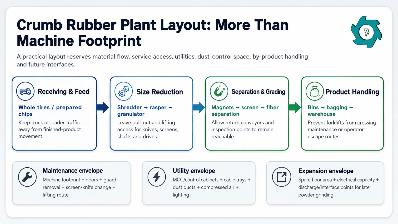
The useful footprint includes more than the machines. Maintenance access, logistics, utilities and future interfaces can decide whether the same process is easy or frustrating to operate.
A crumb rubber line can fit inside a building on a CAD drawing and still be a poor plant layout. The first warning usually appears during installation: a conveyor support lands in the forklift lane, the screen has no room to slide out, the dust duct must cross a service platform, or the electrical cabinets end up beside the only practical maintenance route.
For the current YUXI tire rubber crumb plant, the project boundary can start with whole tires or with prepared wire-free chips, and the published planning inputs already include workshop dimensions, electrical supply, dust control, storage and future expansion. That distinction matters. A whole-tire line has receiving, preparation, primary size reduction and heavier steel handling in front of the crumb section. A downstream granulation module does not.
What Makes a Crumb Rubber Plant Layout Work?
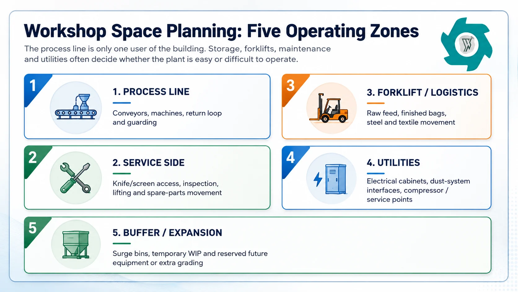
A workable layout gives every material stream and every maintenance task a route. Start with the process direction, then add machine service envelopes, forklift and pedestrian movement, raw and finished storage, electrical and dust-control space, by-product collection, clear height and future expansion. Only after those zones are drawn should the building area be judged adequate.
Start the Layout at the Feed Boundary
The easiest way to make a layout too large—or too small—is to discuss capacity before agreeing where the supplier’s responsibility begins.
Project boundary
Layout consequence
Typical items that must be reserved
Whole tires to crumb rubber
Largest receiving and front-end handling scope
Tire unloading, storage, feeding, possible debeading/cutting, primary shredding, rasper, steel collection, then granulation and finishing.
Pre-shredded tire material to crumb
Front end is smaller, but steel liberation and feed condition still need verification
Buffer feeding, rasper or equivalent liberation stage where required, magnets, granulator, screens, fiber separation and return loop.
Wire-free 10–20 mm chips to crumb
Compact downstream module is possible
Metered feed, granulator, grading, secondary magnetic recovery, fiber separation, dust extraction, product collection and oversize return.
This is also why the decision between coarse product and finer product should be made before the factory drawing is frozen. The site’s existing rubber mulch vs crumb rubber guide separates those product boundaries. Continuing into crumb means more fine cutting, grading, aspiration and product handling, and those functions consume building space even when the incoming tire tonnage does not change.
Plan Operating Space Around the Machines
Machine drawings normally show the equipment body, motor, guards and support frame. They do not automatically show the area a mechanic needs six months later when a screen, shaft, knife set, bearing or conveyor pulley has to come out.
That service space is not decorative margin. We normally treat it as part of the equipment envelope. If a removable component is long, heavy or lifted vertically, the layout must also include the travel path and the lifting method. The same applies to electrical doors, inspection hatches and dust-system cleanout points.
Five different activities compete for the same floor. A good general arrangement drawing shows all five, not only the processing centerline.
1. Keep the material flow easy to read
A mostly one-direction flow is usually easier to operate than a layout with repeated crossovers. Raw material should move toward progressively cleaner product while steel, textile and rejects leave the main route without returning through the clean-product area. EPA’s description of tire-crumb production likewise identifies staged size reduction, steel/fabric removal, screening and oversize return as connected parts of the process.1
The return loop deserves special attention. It carries material that failed the selected screen back toward further size reduction. If that conveyor is squeezed against a wall or made too difficult to inspect, a normal process function becomes a maintenance nuisance. The same principle appears upstream in YUXI’s 10–20 mm size-control guide: recirculation is part of size control, not an afterthought.
2. Draw the forklift routes before placing product bins
A line may have several outward flows at the same time: finished crumb, recovered steel, textile fraction, rejects and empty packaging. When these flows share one narrow aisle, the forklift operator becomes the hidden bottleneck.
One simple layout test is to imagine a routine screen inspection happening while a bulk bag is removed and a steel bin is exchanged. If those three jobs block one another, the drawing needs another pass.
3. Use clear height, not floor area alone
Conveyor elevations, magnetic separators, fiber-separation ducts, dust headers, service platforms and lifting points all use vertical space. A low roof can force long horizontal conveyors or awkward duct bends even when the floor looks generous. Record the usable clear height below beams, cranes, sprinklers and other building services before the supplier fixes conveyor geometry.
4. Raw tire storage can dominate the site
For a whole-tire project, the indoor production line may not be the largest space user. Tire receiving and storage can occupy more land than the machines, and fire, drainage, stacking and permitting requirements vary by jurisdiction. Treat outdoor or indoor tire storage as a separate site-planning problem and review it with the local authority rather than copying a competitor’s yard arrangement.
Power Planning Starts With a Load List, Not One kW Number
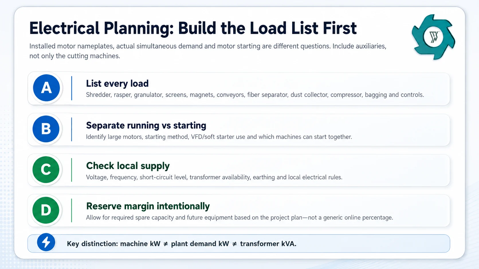
“What is the power of the plant?” sounds like a straightforward RFQ question. It is not. The buyer may mean the sum of installed motor nameplates, the expected running demand, the transformer rating, or the utility connection. Those are related, but they are not interchangeable.
Build the electrical boundary from the actual equipment list. Dust collection, compressed air and material handling are part of the plant load too.
Build the motor and auxiliary schedule
List each driven item separately: shredder where included, rasper, granulator, screens, conveyors, magnets, fiber separator, dust collector fan, rotary valves or filter-cleaning auxiliaries, compressors, bagging equipment and the control system. If the building utilities are inside the project scope, add them as a separate section rather than hiding them inside a machinery total.
The upstream machine sequence changes the list. A project that starts with clean wire-free feed can omit major front-end drives that a whole-tire line needs. The practical difference between the rasper and granulator stages is explained in the site’s rasper vs granulator guide; the machines solve different process problems and should not be deleted from the load list simply because both reduce size.
Check which large motors can start together
A transformer that supports steady running can still be a poor match if a large motor start causes excessive voltage drop. The final answer depends on motor size, starting method, the local network, VFD or soft-starter use where specified, and the permitted start sequence. This is a project electrical-engineering calculation, not a percentage that should be copied from a blog.
Leave expansion capacity only where it has a purpose
Extra capacity is useful when a second granulator, additional grading, automated packaging or a rubber-powder stage is already part of the business plan. “Add 30 percent for safety” is not engineering by itself. State the future load you expect, then reserve the feeder, cabinet, cable route and transformer capacity needed for that defined change.
Dust Control Has to Be Built Into the General Arrangement
Fine rubber processing creates a different housekeeping problem from primary tire shredding. More surface area is exposed, screens separate fine fractions, fiber is moved by air, and every material drop can release light particles. That is why the dust collector cannot be treated as a small accessory added wherever there is leftover space.
There is also a safety reason to take this seriously. OSHA has documented a fatal 2002 explosion at a rubber-recycling plant where tire grinding produced rubber dust that accumulated on building surfaces and in a product bagging bin.2 OSHA’s combustible-dust inspection program includes tire and rubber manufacturing among the industries associated with combustible-dust hazards, and its technical guidance emphasizes effective housekeeping and appropriate controls.34
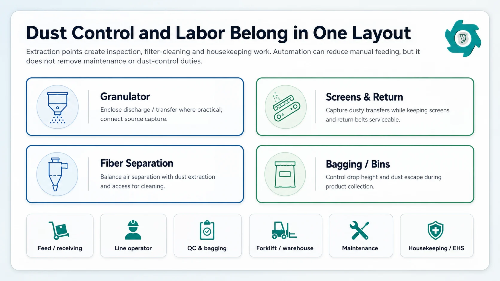
Dust control creates operating work: inspection, filter maintenance, housekeeping and safe collection. Those duties belong in the staffing plan.
Capture close to the release point
Granulator discharge, grading screens, return transfers, fiber separation and final product collection are logical places to review for enclosure and source capture. The goal is to prevent dust from becoming a building-wide housekeeping problem. Duct connections should still leave room to open guards, remove screens and inspect belts.
Do not hide the collector behind the line
Filter access, dust discharge, cleaning air, isolation devices, explosion protection where required, duct inspection and maintenance clearance all consume real space. The correct collector location and protection strategy depends on the dust-hazard assessment, equipment design and local code. A generic “put the bag filter outside” instruction is not enough for a project drawing.
Housekeeping needs a route and a schedule
OSHA’s technical manual calls an effective housekeeping program one of the most important administrative controls for combustible dust.4 In layout terms, that means ledges, cable trays, elevated platforms and the tops of equipment must be reachable. A beautifully enclosed line that cannot be cleaned safely is not a finished dust-control design.
Estimate Labor by Workstation, Then Combine Roles Carefully
Automation changes where people stand. It does not make the plant labor-free.
A smaller line may have one operator monitoring several machines, while another person handles feed and finished bags. That can work when feed is consistent, packaging is simple and the site has shared maintenance support. It stops working when the same person is expected to feed the line, change steel bins, sample product, clear alarms and move a forklift at the same moment.
Work function
What the person is actually doing
Layout implication
Receiving / feed
Unload or stage feed, inspect obvious contamination, operate loader or feed conveyor.
Safe vehicle approach, staging buffer and visibility into the feed system.
Line operation
Monitor load, interlocks, screens, return flow, magnets and alarms.
Control position with useful sight lines and safe access to inspection points.
Product / by-products
Change bags or bins, move crumb, steel and textile, label product.
Forklift lanes and storage that do not cross maintenance work.
Quality control
Collect samples, check particle distribution and contamination, retain records.
Sampling point and a clean place for basic QC work.
Maintenance
Knife/screen work, bearings, belts, sensors, lubrication and planned shutdown tasks.
Service clearance, lifting route, spare-parts storage and lockout access.
Safe access around and above equipment; dust collection points that can be serviced.
Use these functions to build the shift roster. Some functions can be combined at a small automated plant; others may require dedicated people as throughput, bagging frequency or forklift traffic increases. Also plan break coverage. A line that requires one person to remain at the controls cannot simply lose that station for half an hour.
Capacity planning and labor planning should use the same production basis. If the plant is intended to run long shifts at a tight finished fraction, the return loop, wear rate, packaging frequency and housekeeping workload all rise in importance. The existing rubber-mulch capacity guide makes the same broader point upstream: annual accepted output depends on the complete operating system, not only the biggest machine’s brochure rate.
Same Equipment, Two Very Different Layouts
Consider a downstream crumb module with a feed conveyor, granulator, grading screen, return conveyor, secondary magnet, fiber separator and bagging point. On the first drawing, the machines form a neat rectangle. The return conveyor runs against the wall, finished bags leave through the center aisle, and the dust header crosses above the screen.
It looks compact. It is also awkward. The wall blocks return-conveyor inspection, a full bulk bag stops anyone approaching the granulator service side, and the screen cannot be lifted without moving ductwork.
Turn the same line and give the return loop a service side. Put finished-product removal at the clean end of the building and move steel/fiber collection to the opposite side. The equipment list has not changed. The square metres may barely change. But routine work no longer fights itself.
This is why an equipment supplier should ask for building drawings early. Length, width and height matter, but door positions, columns, floor pits, crane coverage, utility rooms and yard access often matter just as much.
Can the Plant Fit in an Existing Building?
Yes, sometimes with less modification than expected. But a usable building check should happen before the final quotation, not after the containers are shipped.
Clear dimensions: usable length, width and height below beams and services.
Structure: floor loading and foundation requirements to be checked by the project civil/structural engineer.
Access: largest machine delivery route, door size, turning area and rigging space.
Maintenance: screen, knife, shaft and motor removal paths; lifting points or crane access.
Electrical: voltage, frequency, transformer and switchgear space, cable route and local standard.
Dust: extraction points, duct route, collector/service space and project-specific hazard controls.
Logistics: raw feed, finished crumb, steel, textile, packaging and forklift movement.
Fire / storage: local requirements for tire and rubber storage, egress and protection systems.
Expansion: realistic space and utility interfaces for later grading or powder production.
What to Send Before Requesting the Final Layout
A manufacturer can prepare a much better general arrangement when the request includes real site constraints. A practical layout packet should contain:
Feed & product
Tire types, starting material, target finished fraction, steel/fiber limits, packing method and required finished tonnes per hour.
Building
Dimensioned floor plan, clear height, columns, doors, pits, existing cranes, restricted zones and photographs.
Electrical
Voltage, frequency, available transformer capacity, local component/installation requirements and planned expansion.
Site logistics
Truck route, raw tire storage, forklift type, product warehouse, steel/textile disposal route and loading area.
Environmental / safety
Dust and ventilation requirements, local fire review, noise boundary where relevant and any owner-specific EHS standard.
Operating plan
Shifts, staffing concept, maintenance hours, target automation level and whether the site will run while another line is being serviced.
Layout Mistakes That Usually Cost More Later
Buying from a floor-area claim
A supplier’s published area may include only the machines. Ask what storage, aisles, maintenance and utilities are excluded.
Putting every conveyor against a wall
Compact drawings look efficient until rollers, belts, sensors or return material need attention.
Forgetting elevated maintenance
Screens, magnets and ducts may be reachable only from platforms. Those platforms need safe access and cleaning routes.
Sizing power from motor sum alone
Connected kW is a starting point. Simultaneous demand, motor starting, auxiliaries and destination electrical rules still need engineering.
Adding dust control after equipment placement
Late duct routing can block screen removal, platforms and cranes. Extraction belongs on the first serious general arrangement.
Calling automation “no labor”
Someone still receives material, handles product, checks quality, maintains wear parts and manages housekeeping.
Crumb Rubber Plant Layout FAQ
How much space does a crumb rubber plant need?
There is no reliable universal floor-area number. Space depends on whether the project starts from whole tires or prepared wire-free chips, the capacity and product fractions, conveyor arrangement, maintenance clearances, raw-material and finished-product storage, dust-control equipment, forklift routes and future expansion. Ask for a general arrangement drawing tied to your actual building dimensions rather than buying from a square-metre claim.
How much electrical power does a crumb rubber plant use?
Build the answer from the project motor and auxiliary load list. Add shredding or rasping equipment when the line starts from whole tires, then include granulation, screening, magnets, conveyors, fiber separation, dust collection, compressed air, bagging and controls. The connected motor total is not automatically the same as simultaneous demand or transformer size; starting method and local electrical design also matter.
Where should dust collection be connected on a crumb rubber line?
Typical dust-generating points include fine size reduction, screens, return transfers, fiber separation and product collection. Capture should be designed close to the source where practical, while ducts, filters and collection equipment remain accessible for inspection and cleaning. Final design needs a project-specific dust-hazard and local-code review rather than a copied duct size or collector location.
How many workers are needed per shift?
Staff the work, not a generic headcount. Typical duties include feed receiving, line control, product and by-product movement, quality checks, bagging, forklift work, maintenance, housekeeping and supervision. Smaller automated plants may combine several duties, while larger or multi-shift sites usually separate them. Coverage for breaks, maintenance and abnormal conditions should be planned before commissioning.
Should the first layout include future rubber-powder expansion?
If fine powder is a realistic second phase, reserve the interface now. Leave floor area, clear height, discharge and conveyor connection points, electrical capacity, dust-control space and storage for the later grinding and classification section. This does not mean buying the powder line immediately; it means avoiding a workshop rebuild when the market changes.
Plan the Workshop Before Freezing the Equipment List
Send your tire mix, starting material, finished crumb specification, target capacity, building dimensions, clear height, local power supply and operating plan. YUXI can use those inputs to develop the process boundary and general arrangement around real maintenance, dust-control and material-handling requirements.
External Engineering References
U.S. Environmental Protection Agency. Tire Crumb Questions and Answers — overview of tire size reduction, steel/fabric removal, screening and oversize return. EPA.
U.S. Occupational Safety and Health Administration. Combustible Dust; Proposed Rule — includes the documented 2002 rubber-recycling dust explosion in Vicksburg, Mississippi. OSHA.
U.S. Occupational Safety and Health Administration. Combustible Dust National Emphasis Program. OSHA.
U.S. Occupational Safety and Health Administration. OSHA Technical Manual, Section IV, Chapter 5 — combustible dust controls and housekeeping. OSHA.
Marie has 8+ years of experience in tire shredding and recycling equipment,with a focus on tire shredders,rubber recycling machines,TDF production,rubber crumb processing,and complete tire recycling systems.