




A factory acceptance test should answer a specific question: does the assembled TDF line match the purchase boundary and produce defensible results before it is dismantled and loaded for shipment?
A TDF shredder RFQ defines what the supplier must provide; the FAT determines whether those requirements have actually been demonstrated before shipment. Site acceptance remains a separate step because shipping vibration, reassembly, foundations, utilities and the buyer’s operating crew introduce conditions a factory floor cannot reproduce.
1. Turn the Purchase Order Into a Testable Acceptance Matrix
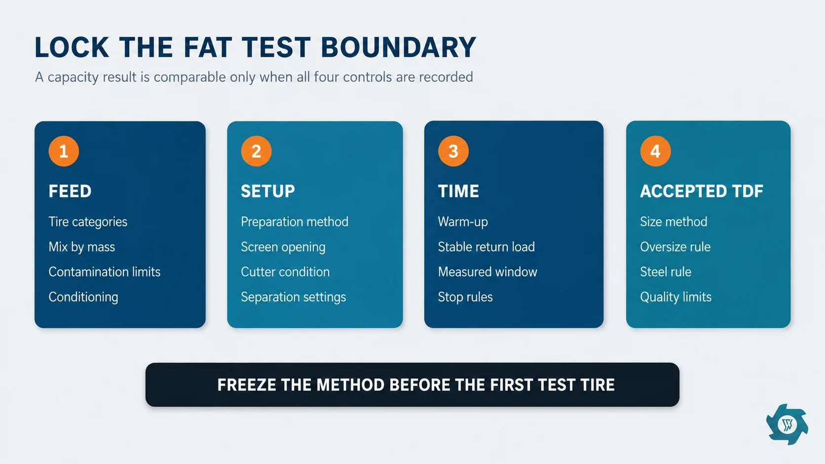
Put each requirement into one row with five fields: requirement, test method, measuring device, acceptance criterion and evidence file. If “capacity” has no product boundary or “50–80 mm” has no sampling method and oversize rule, the FAT team will be negotiating after the tires are already on the floor.
Freeze the revision numbers for the general arrangement, motor list, I/O list, electrical drawings, bill of supply and approved deviations. Mark equipment that cannot be erected at the supplier’s factory. A buyer should not reject an uninstalled field conveyor as a FAT failure if the agreed test boundary excluded it; equally, an excluded conveyor must not silently appear in a “complete line passed” statement.
| Boundary item | Record before testing | Why it changes the result |
|---|---|---|
| Feed | Tire types, quantities, approximate mass, contamination exclusions and conditioning | Truck casings, passenger tires and pre-cut sections impose different bite, torque and steel loads. |
| Preparation | Debeading, sidewall cutting, quartering or whole-tire feed | A pre-cut test cannot validate a quoted whole-tire duty. |
| Machine setup | Screen opening, cutter arrangement and condition, gaps, magnet positions and control recipe | These settings determine recirculation, size distribution and practical output. |
| Time | Warm-up, stabilization and measured-window rules | Short bursts can avoid heat and circulating-load effects. |
| Accepted product | Size method, oversize allowance, exposed/loose steel rule and conditional quality limits | Only material meeting this definition belongs in accepted capacity. |
2. Confirm That the FAT Equipment Is the Equipment Being Shipped
Read nameplates against the approved motor and equipment lists. Record serial numbers where available. Check reducer ratios, cutter count and width, screen marking, conveyor width, magnet model, installed electrical components, lubrication units, hydraulic power packs, access platforms and guarding. Photograph identification plates and major assemblies in a logical sequence.
Temporary factory equipment needs an explicit label. A larger test transformer, borrowed conveyor, external oil cooler or workshop dust collector can make a demonstration possible, but it must not be mistaken for delivered scope. Note its function and the buyer-side utility or field equipment needed to replace it.
The current YUXI Tire TDF Plant describes a mechanical route using preparation where required, shredding, screen-controlled discharge and oversize return.
3. Complete Static, Dry-Run and Safety Checks Before Feeding Tires
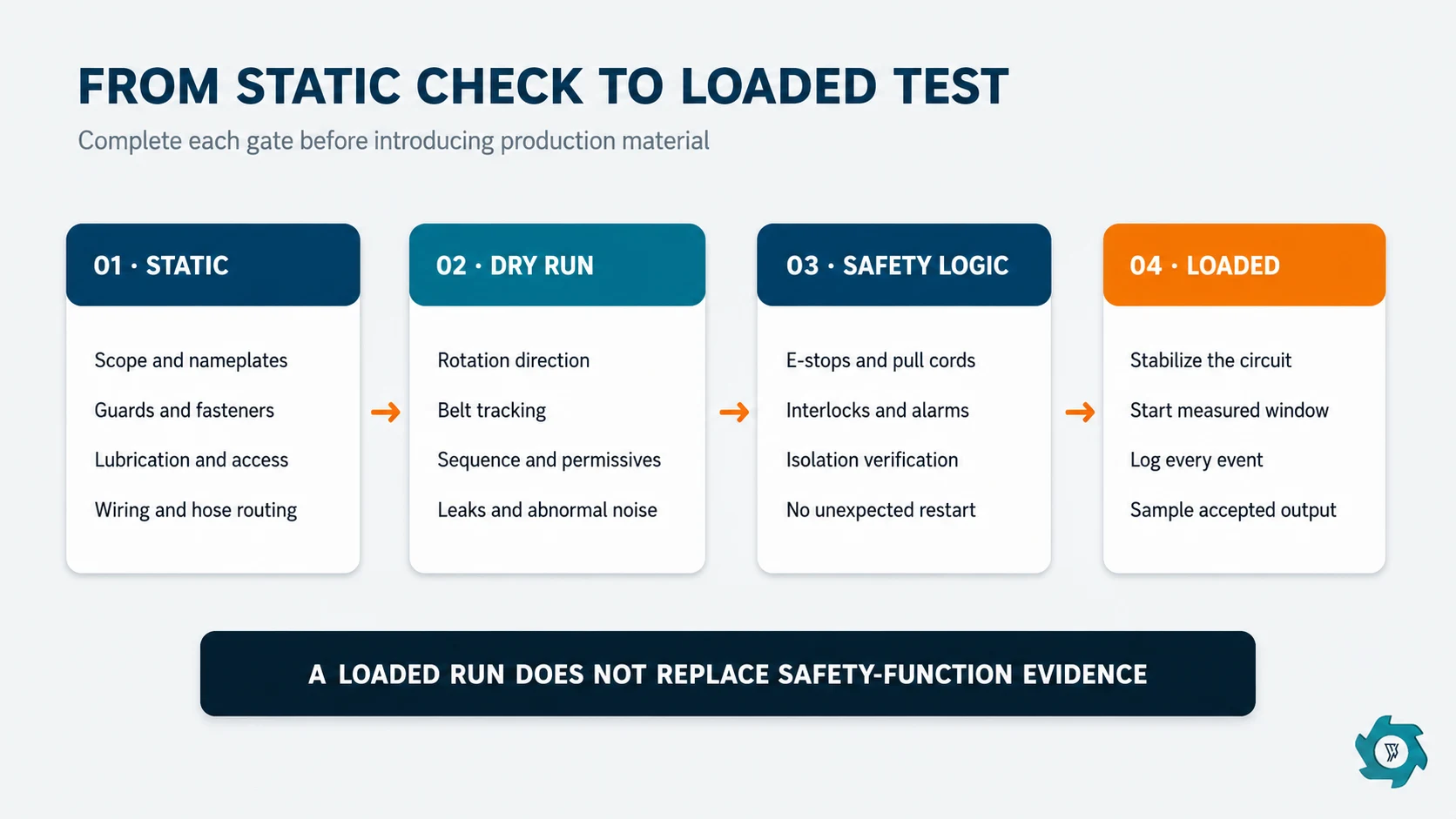
Do not use production material to discover reversed conveyors, dry gearboxes or incomplete guards. Start with alignment, fasteners, lubrication, hose routing, rotation direction, belt tracking, accessible maintenance points and housekeeping. Verify HMI language, units, alarm history, user levels, parameter backup and the final software version.
Function-test every emergency stop, pull cord, guard interlock, overload response, permissive and restart condition that is inside the FAT boundary. Record both the initiating device and the resulting safe response. A reset should not create an unexpected automatic restart. Simulate loss and restoration of control power where the agreed design permits it.
Electrical evidence can include protective-bonding results, insulation or voltage tests where applicable, circuit protection, conductor and terminal identification, enclosure condition and drawing conformity. The German Social Accident Insurance’s IFA publishes a testing sequence based on IEC 60204-1; use the edition and conformity route named in the contract rather than claiming that a generic FAT itself grants certification.2
4. Stabilize the Line Before Starting the Measured Window
A TDF circuit does not reach representative duty when the first tire reaches the shredder. The screen and return conveyor need time to establish a circulating load; motors, hydraulics and bearings begin to warm; the hopper develops a realistic bed; and the operator settles into the intended feed rhythm.
Write the stabilization trigger in observable terms. Examples include a minimum running time, normal material present on the return belt, stable feed cadence and key temperatures or currents no longer moving rapidly. Do not count stabilization feed as measured test input unless the protocol says so. Keep it in the mass reconciliation as preloaded or retained material.
Classify interruptions while they occur
Use a shared event log with start time, finish time, cause, action and whether the clock continued. At minimum distinguish:
- planned observations or agreed sampling stops;
- feed starvation caused by factory handling;
- foreign-object or nonconforming-feed events;
- automatic reversals that are part of normal control;
- manual clearing, bridging or jams;
- equipment, electrical or control faults;
- buyer-requested inspections.
Report gross elapsed time, equipment running time and the acceptance time basis side by side. For performance comparison, the accepted-ton operating boundary is more useful than an unqualified “tons per hour.”
5. Measure a Material Balance, Not Just the Feed Hopper
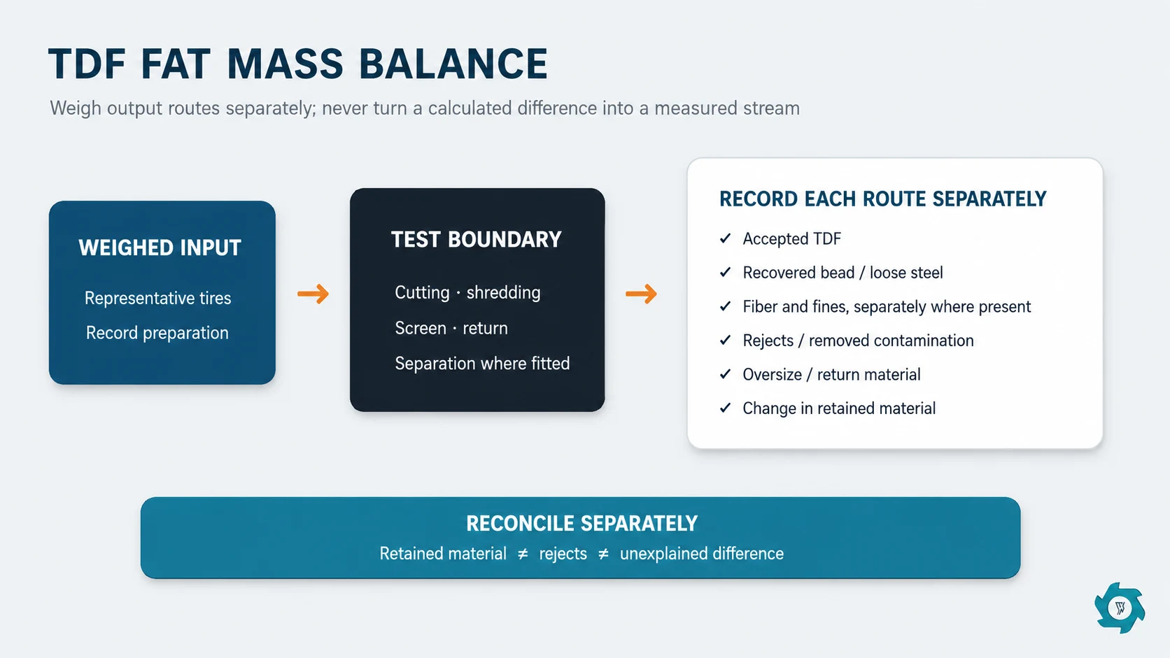
During the agreed window, weigh the input and every material stream that crosses the FAT test boundary. The exact external outputs depend on configuration, but they can include accepted TDF, recovered bead or loose steel, separately extracted fiber or fines, and rejects or removed contamination. Record the change in material retained in hoppers, cutting chambers and conveyors separately.
Do not count internal oversize return as another output. Material that leaves the screen and returns to the shredder remains inside the test boundary. Measure the return flow separately as a circulation KPI because it affects equipment duty and accepted capacity, but do not subtract it again in the mass balance unless that material physically leaves the defined boundary.
Report the difference as its own number. Dust migration, scale resolution, spillage, moisture change and inaccessible hold-up can all contribute. Set a tolerance before the test and investigate any result outside it.
6. Calculate Capacity at the Accepted-Output Boundary
A screen may circulate a large fraction of the cut material. The FAT capacity metric should use only product discharged during the measured window that meets the agreed acceptance rule.
Freeze the denominator before testing. The contract may use continuous-window elapsed time or defined net running time, but the same rule must be applied to the accepted-output mass and the event log. If test logistics require batch weighing after the window, seal and identify each container so material cannot cross between stabilization and measured lots. State whether wet mass or a moisture-corrected basis is used. Do not convert a brief peak conveyor reading into a continuous-line guarantee.
Log motor current or power, hydraulic pressure and temperature, bearing temperatures where instrumented, and overload/reversal events on a common clock. These observations explain the run; they do not by themselves prove site energy consumption. Factory utilities, incomplete dust systems and temporary conveyors can differ from the installed plant.
7. Sample Chip Size and Steel Without Cherry-Picking
Take increments across the entire measured window or from a controlled composite lot. Preserve the original sample ID, time, stream, mass and custody. ASTM D6700 provides guidance for scrap tires recovered for fuel value and emphasizes that TDF decisions involve handling, feeding, combustion and environmental considerations.3 The U.S. EPA also identifies ASTM D6700 as the relevant standard for shredded TDF physical properties.4
For size, record the agreed method: maximum dimension check, screen/sieve classes, sample mass, number or mass basis for oversize, and treatment of long wire projections. For steel, distinguish loose liberated metal from steel still embedded in rubber, and use the receiver’s written method. A magnet demonstration can show removal function, but it does not quantify all embedded steel.
When validating different tire mixes, hold the preparation, screen, cutters, control setting and time basis constant. The engineering differences between passenger and truck casings are treated separately in the passenger-versus-truck TDF comparison; mixing categories without recording their masses makes the FAT difficult to reproduce.
8. Test Control Responses, Not Only Steady Production
Under an approved and safe method, verify high-load response, automatic reversal limits, downstream-stop permissives, blocked-sensor alarms, conveyor sequence, emergency stop and controlled restart. Confirm that material cannot continue feeding into a stopped downstream machine unless the design specifically provides safe accumulation.
Check data retention after a power cycle, recipe access, alarm timestamps, language, units, remote-access permissions and backup files. Save the PLC/HMI software version and parameter set delivered with the plant. Remote access should have an agreed owner, authorization method and disable path.
9. Inspect Maintainability and the Shipment Package
Ask the supplier to demonstrate a realistic blade inspection or representative service task under the energy-control procedure. Confirm access for screen removal, magnet cleaning, lubrication, belt tensioning, sensor replacement and jam clearing. Note required lifting points, special tools, blocking provisions and component weights. Maintenance access that exists only before adjacent conveyors are installed is a layout issue.
Before packing, reconcile loose-shipped parts, cables, sensors, guards, fasteners, spares and tools against a packing register. Photograph match marks and cable labels. Protect machined faces, exposed shafts, hydraulic ports, electrical enclosures and corrosion-sensitive parts. Record preservation method and storage limits, especially when ocean freight or delayed erection is possible.
The documentation package should contain as-built general arrangements, foundations and loads, utility requirements, electrical drawings, I/O and motor lists, manuals, lubrication schedule, wear-parts list, spare-parts list, certificates required by contract, software backups, FAT records and open-item register. Training topics and site commissioning responsibilities belong in the handover record even if delivery occurs later.
10. Use Three Dispositions and a Controlled Punch List
| Disposition | Use it when | Required record |
|---|---|---|
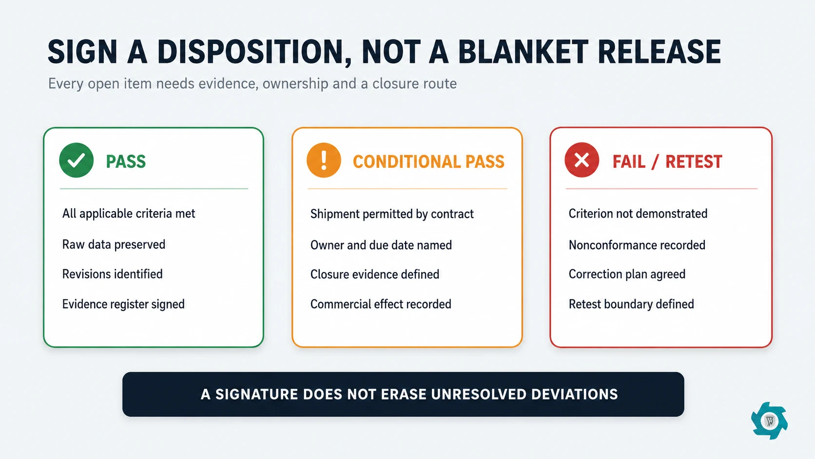
| Pass | All applicable acceptance criteria are met. | Signed results, raw data, samples/evidence register and software/document revisions. |
| Conditional pass | Open items do not invalidate the demonstrated function and shipment is contractually permitted. | Each item has an owner, remedy, evidence required, due date and commercial disposition. |
| Fail / retest | A safety-critical function, scope item or performance criterion is not demonstrated. | Nonconformance, root issue where known, correction plan and defined retest boundary. |
State the physical location, expected condition, proof required and who may accept the evidence. If a correction can alter performance—cutter change, screen change, motor/control change or return-loop modification—define whether a full or partial retest is required.
11. Buyer’s Witness Checklist
- Approved specification, drawings and deviations are at the FAT station.
- Test feed and feed preparation match the written protocol.
- Scales and instruments have identifiable ranges and calibration/status evidence.
- Safety observers, exclusion zones and energy-control responsibilities are assigned.
- The equipment and any temporary factory aids are clearly distinguished.
- Static, no-load and safety-function checks are completed before loaded testing.
- Stabilization and the measured window are separately logged.
- Input, external output streams and retained material are reconciled according to the defined boundary; internal return flow is recorded separately as a circulation KPI.
- Samples are representative, labeled and retained as agreed.
- Interruptions and automatic reversals remain in the raw event log.
- Capacity is calculated from accepted output, not only fresh feed.
- As-built documents, software backups and packing records are revision controlled.
- Every deviation receives a disposition, owner, due date and closure evidence.
FAQ
What is the main purpose of a TDF plant FAT?
The FAT checks whether the assembled equipment matches the contracted scope and can safely perform the agreed functions under a written test boundary before shipment. It reduces uncertainty; it does not replace site commissioning.
How long should a TDF performance run last?
There is no universal duration. Set an agreed stabilization period followed by a continuous measured window long enough to expose recirculation, heating, bridging, overload and intervention patterns. State which stops pause or invalidate the window.
Should throughput be based on tire input or finished TDF output?
Record both, but judge saleable capacity on accepted TDF output that passes the agreed size and quality rules. Fresh-feed rate alone can hide oversize return, rejects and material retained in the line.
Can a video FAT replace attendance?
A witnessed live video can support verification when camera views, scales, instrument readings, sample sealing and record transfer are agreed in advance. Edited highlight footage is not equivalent to an observable test.
Does FAT approval mean the plant is ready for production at site?
No. Transport, reassembly, foundations, utilities, guarding interfaces and local operating conditions still require site checks, commissioning and training. FAT approval should be tied only to the defined factory test scope.
References and Source Notes
- OSHA, 29 CFR 1910.147 — The control of hazardous energy. Used for energy-isolation, lockability and verification principles.
- IFA/DGUV — Testing of the electrical equipment of machines. Identifies its checklist sequence as based on IEC 60204-1.
- ASTM International — ASTM D6700-19, Standard Guide for Use of Scrap Tires as Tire-Derived Fuel. Scope and TDF engineering context.
- U.S. EPA archived FAQ — Tire-Derived Fuel. Historical EPA page identifying ASTM D6700 in connection with shredded TDF physical properties; the current ASTM edition is cited separately above.
Prepare a Testable TDF Line Proposal
Send your tire mix, target chip specification, accepted-output capacity, steel requirement and intended test method. YUXI can align the equipment boundary and FAT records with the project conditions.