




A tire bead cutting machine is often described as a simple front-end station. That description hides the important part: it combines a rotating worktable, a powered cutter, a heavy and springy tire, clamping, and—on many machines—hydraulic motion. A safe station is not created by one emergency-stop button. It is built by defining what an operator may do during production, what requires a controlled stop, and what requires verified isolation.
In a typical waste tire bead cutting machine process, the tire rotates while an alloy cutter follows the bead circumference to separate the bead ring or bead-sidewall section. The safety limits need to be clear because the tire can shift while it is being cut. The blade is also working close to steel-reinforced sections, and poor tire positioning can cause sudden movement before the cut is finished.
In normal operation, the operator works from outside the guarded zone and uses the controls provided for the machine. If the job changes from loading, observing or unloading to clearing, adjusting, measuring, cleaning or servicing, stop treating it as normal production. Use the site’s documented energy-control procedure and competent personnel.
Start With the Operating Boundary, Not PPE
PPE is useful, but it is the final layer, not the machine’s main protective method. A better first question is: where can a person be while the table rotates, a clamp moves or the cutter travels? That answer should be visible in the layout, guarding and work instructions. The UK Health and Safety Executive notes that safeguarding can include guards, interlocks, two-hand controls, light guards and pressure-sensitive devices, and advises users to check that a machine is complete, safeguarded and free of defects before use.1
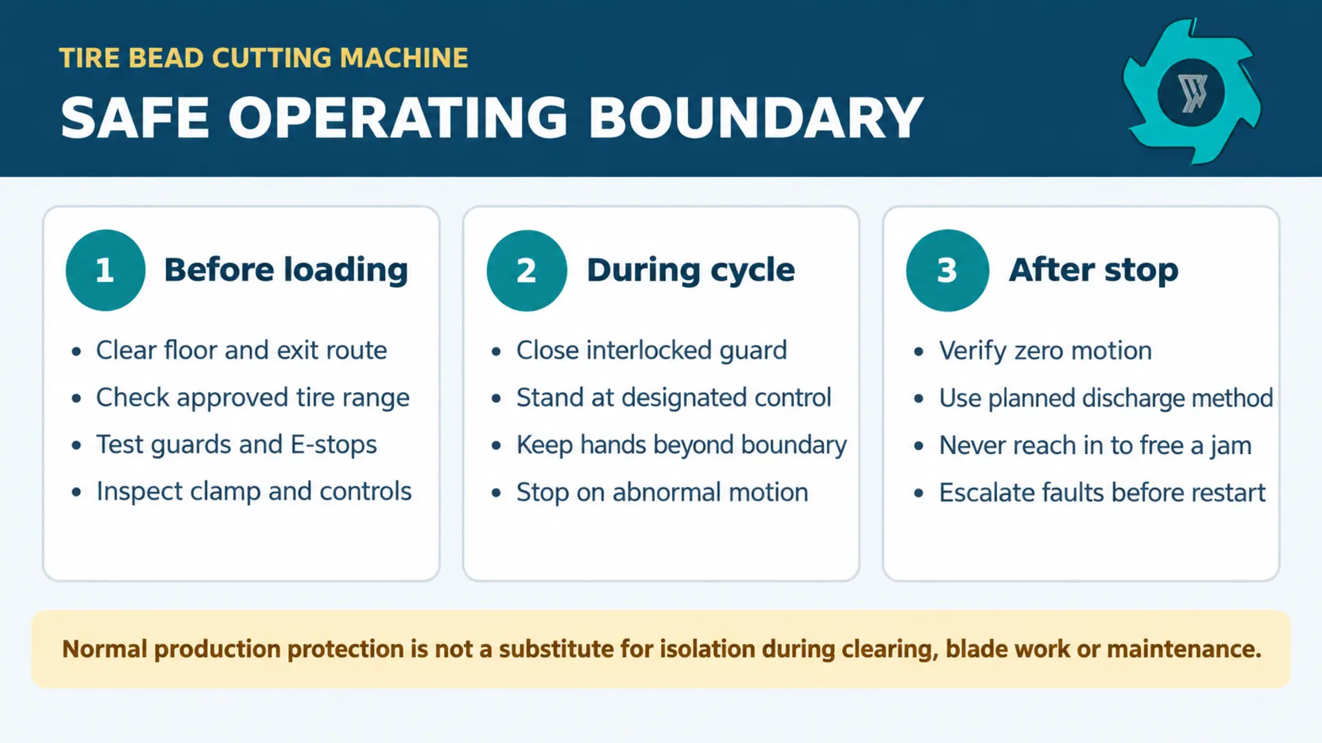
For a bead-cutting station, divide work into three states.
Normal production includes presenting an approved tire, operating from the intended control position, and removing material only after the machine has reached the defined safe state.
Controlled stoppage includes an operator pressing stop because something looks wrong, then keeping people out while a supervisor or authorized person decides the next step.
Servicing access includes any task where someone enters the guarded zone or relies on the machine remaining still.
The Hazard Map: More Than the Blade
The blade is obvious. The less obvious hazards often cause the unsafe workaround: a tire that is not centered, a bead section that catches, a clamp that does not fully hold, a temporary pile blocking the exit, or a worker trying to recover lost cycle time. The risk review should follow the material from the floor buffer to the next collection point rather than ending at the cutter head.
Rotating tire and table
Pinch, entanglement and struck-by hazards can occur at the tire, rim-facing area, table edge and any adjacent fixed surface. Keep access points outside the reach zone; do not permit hand guidance once movement begins.
Cutter and clamp movement
The cutting and clamping areas can trap, crush, or release stored energy. A guard is not enough just because the opening looks covered; it also needs to prevent someone from reaching into the hazard area.
Heavy, unstable feed
Truck and mixed tires can roll, rebound or require awkward turning. A safe process includes a defined infeed buffer, floor condition, handling aid and discharge method—not an operator improvising with a bar.
Released material
A separated ring or sidewall section can shift after the cut. Plan where it lands, where it is collected, and who removes it after the verified safe state.
There is no universal “safe tire size” based only on diameter. Tire family, width, weight, sidewall condition, bead construction, mud, embedded debris and deformation all affect how it sits on the table. In practice, a written approved-tire envelope is much more valuable than a vague instruction to “be careful with large tires.” The envelope should identify the machine configuration, maximum and minimum dimensions, excluded tires, loading method and any special set-up needed.
This is distinct from the wider process question of why bead rings are removed before downstream size reduction. If your project needs that process decision, see why remove tire beads before shredding.
Build a Work Cell That Makes the Safe Choice Easy
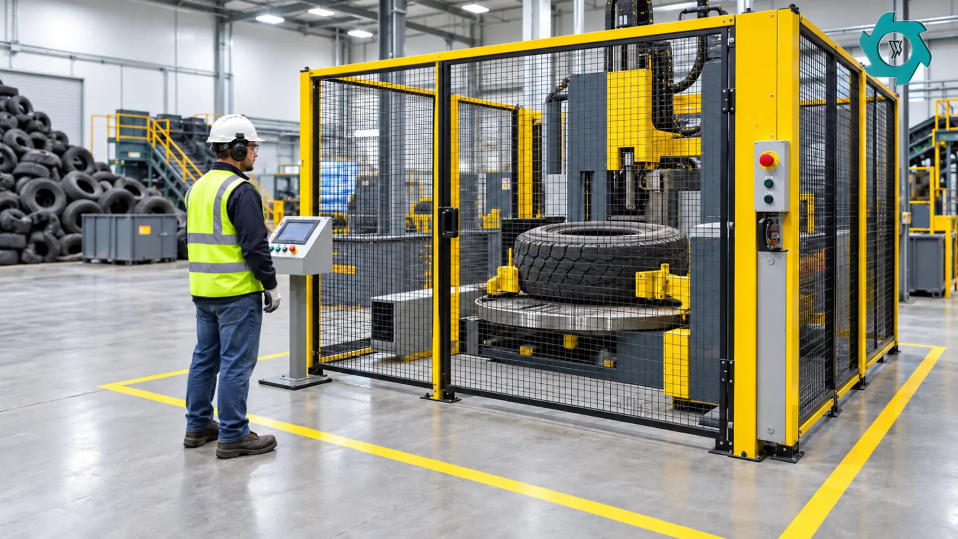
A machine can arrive with sound guarding and still become a poor work cell if the floor layout forces people to cross the discharge route, reach over a barrier, or carry bead rings through the loading side. Before release for production, walk one full cycle with the actual operator: receive tire, stage tire, load, align, close guard, start, observe, stop, release, collect two outputs, reset, and remove waste. Any unnecessary crossing, lifting or reach is a design finding.
| Cell feature | What good looks like | Warning sign |
|---|---|---|
| Infeed buffer | Stable tire storage with a clear route to the loading point; size and condition are visible before lifting. | Loose piles, hidden debris, tires leaned against guards or a worker rolling tires across a shared aisle. |
| Safeguarded zone | Fixed or interlocked guards cover foreseeable access to table, cutter and clamp movement. | A normal task requires reaching around, over or through the guard. |
| Control point | Operator can see the relevant area while standing beyond the danger boundary. | Operator has to lean into an opening to judge tire position. |
| Discharge and bins | Main tire body and bead-sidewall output have assigned landing/collection areas. | Parts accumulate against the guard or are picked up while motion may still occur. |
| Emergency access | Stops, isolators and escape route are unobstructed and known to every shift. | Bins, pallets or hoses block controls or the exit path. |
Emergency-stop devices are important for responding to danger; they do not replace the normal stop sequence, guard interlocking or maintenance isolation. Treat their placement and reset behavior as part of a documented functional check. A reset should not, by itself, create a new hazardous motion. The same principle applies to guard doors: an opened guard should prevent hazardous movement from starting until the guard is closed and the normal restart command is deliberately given.
A Deliberate Normal-Production Sequence
Written procedures should use observable checkpoints. “Operate safely” is too vague to coach or audit. The following sequence is a practical structure; adapt it to the supplied manual, risk assessment and local rules.
- Prepare the station. Clear the floor, collection bins and walkway. Confirm the planned tire family matches the approved operating range. Look for loose wire, damaged sidewalls, exposed metal, trapped rims or unusual deformation that needs escalation.
- Inspect before energizing work. Check guards, interlocks, control devices, clamp condition, cutter condition, hydraulic leaks, visible cables and the normal discharge path. Defects are not “watch items” if they affect a protective function.
- Load with the planned method. Use the designated handling aid when the tire is too heavy, bulky or awkward for the assigned person. Center and restrain the tire according to the machine instruction. Do not use body weight, improvised bars or a helper’s hands inside the intended hazard zone to force alignment.
- Close and verify the safeguard. Ensure everyone is clear, guards are in their intended state and the operator is at the designated control location. Start only through the normal sequence.
- Observe from outside the boundary. Watch for abnormal movement, rubbing, clamp slip, unusual vibration, odor, leakage or a cut path that is not behaving as expected. An operator should be empowered to stop at the first credible sign, not after several reset attempts.
- Remove only after the defined safe state. Wait for confirmed cessation of movement and follow the approved release/discharge procedure. Sorting and carrying are separate work steps; keep them out of the loading and guard-access path.
For set-up and commissioning detail, use the related tire bead cutting machine installation guide. Once the station is commissioned, daily safety still depends on repeated pre-start confirmation and consistent work-cell discipline.
When the Cycle Is Not Normal: Stop Before You Diagnose
Bead cutting sometimes exposes unpredictable tire conditions. A tire can sit unevenly, a cut can deviate, material can bind, a guard can fail to latch, or the machine can stop mid-cycle. The unsafe moment usually takes place: someone tries to save time by opening a guard, repeatedly pressing reset, or putting a tool into the cell while another person remains at the controls.
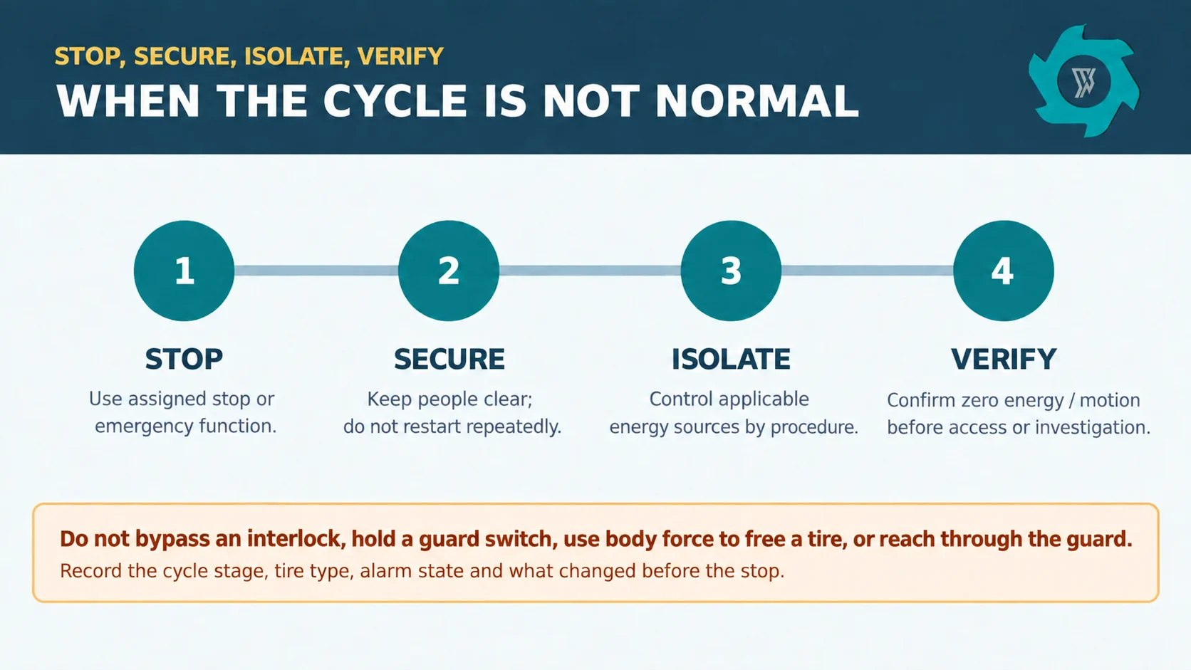
Keep the response simple and familiar: stop the machine, make it safe, isolate the energy, verify it is secure, then find the cause. The exact method depends on the machine and site procedure, but the escalation trigger should be unambiguous. If anybody needs access beyond the normal operator boundary, if a guard is opened for fault recovery, or if stored energy could move a cutter, clamp or table, move to the site’s energy-control process.
Do not make a reset a diagnosis. Record the cycle stage, tire category, the position of the tire and clamp, alarm or indicator condition, recent maintenance, and any sound or motion that came first. This makes a repeatable problem visible to the responsible technician. It also avoids destroying evidence by cycling power or bypassing an interlock.
For fault-specific process observations such as repeated cut-path error, material variation or stops during a cycle, see tire bead cutting problems and troubleshooting.
Isolation and Lockout/Tagout: Control Every Relevant Energy Source
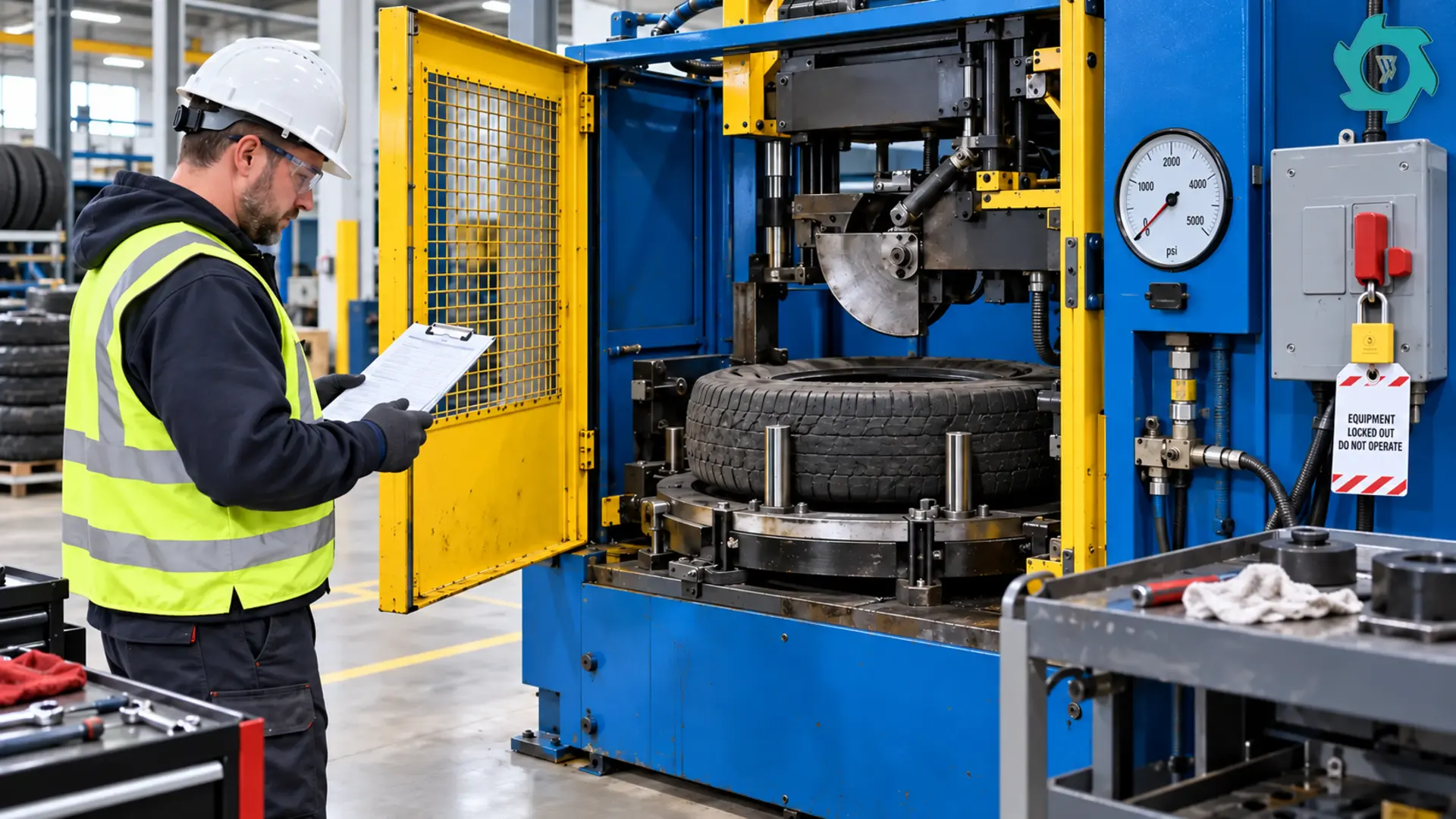
OSHA’s lockout/tagout standard covers servicing and maintenance where unexpected energization, start-up or release of stored energy could cause injury.2 For a bead cutter, that can mean electrical supply, hydraulic pressure, mechanical movement or gravity/stored force in a component. The exact energy-isolation points and dissipation steps must come from the delivered machine documentation and the employer’s authorized procedure—not from a generic internet checklist.
For a site procedure, distinguish three concepts that are often mixed up.
A normal production stop ends the cycle through the controls.
An emergency stop responds to an immediate dangerous condition.
Energy isolation controls the energy sources before servicing or maintenance. Guarding protects people during normal production; isolation protects people when the protective boundary must be opened or removed. OSHA also explains the relationship between machine-guarding standards during normal production and energy control during servicing.3
Before authorized service access, the procedure should establish:
- which energy sources apply to this configuration and where each isolation device is located;
- how residual hydraulic, pneumatic, mechanical or gravitational energy is released, restrained or blocked;
- how locks and tags identify the authorized person;
- how a zero-energy state and zero motion are verified using the site-approved method;
- how group work, shift changes, contractors and return-to-service are controlled; and
- who may remove a lock and under what documented exception process.
Blade changes deserve their own task-based procedure. It should define the blade/tool condition that triggers change, the isolation boundary, secure support for components, required tooling, cut-resistant handling precautions where appropriate, torque/fastener verification, guard reinstatement and a controlled test before production release.
Training Must Prove Decisions, Not Just Attendance
Operators do need to recognize the safe operating boundary, know what they are authorized to do, and stop when a condition lies outside that boundary. Training should use the actual tire mix, cell layout and controls. A supervisor can verify readiness by asking an operator to explain the difference between normal unloading, a controlled stop, and a task that needs authorized isolation.
| Role | Must be able to do | Must not be asked to do |
|---|---|---|
| Operator | Perform pre-start check, load approved tires, run normal cycle, stop and report abnormal conditions, keep the cell orderly. | Bypass safeguards, adjust protected mechanisms, enter the zone to free a jam, or perform energy isolation unless separately authorized and trained. |
| Supervisor | Confirm work-cell conditions, investigate trends, protect time for corrective action and prevent production pressure from overriding stop rules. | Approve a workaround that changes the risk boundary without documented assessment. |
| Authorized maintenance person | Use the documented isolation procedure, diagnose faults, maintain safeguards and confirm controlled return to service. | Rely on a verbal “it is off” confirmation or release the machine with guards/safety functions unresolved. |
At shift handover, record more than throughput. Include outstanding faults, guard/interlock issues, cutter condition, tire categories that caused difficulty, isolation status, open work orders and whether the machine is safe for normal production.
Safety Questions to Put Into the RFQ and Acceptance Test
Safety should be specified as a testable scope. The buyer should request a machine-specific safety-function schedule and ask how the supplied configuration handles foreseeable access. ANSI B11.19 provides performance requirements for the design, construction, installation, operation and maintenance of safeguarding and other risk-reduction measures; the final selection still has to be based on a task-specific risk assessment.4
- What guards, interlocked access points, stops, isolators and control devices are included in the quoted scope?
- Which access is expected during normal production, cleaning, cutter change and fault recovery?
- What is the approved tire envelope, including size, weight, construction and exclusions?
- How is tire restraint verified before the cycle begins, and what conditions prohibit start?
- Which energy sources must be isolated for blade work, jam recovery and maintenance?
- What manuals, wiring/hydraulic diagrams, safety labels, spare-parts list and operator training records are supplied?
- What functional checks are demonstrated at FAT, and what site checks are repeated at commissioning?
Pre-processing is only one part of an overall line. If a project also uses bead-wire extraction instead of bead-sidewall cutting for some tire families, compare the safe handling route with the tire wire drawing machine process. The safe choice depends on the incoming tire condition, the required downstream feed and the work cell.
Daily Supervisor Safety Check
- Guard panels, doors, hinges and interlocks are present, intact and operating as intended.
- Emergency stops, normal stops, controls and isolators are accessible and not obstructed.
- No leak, loose fastener, damaged cable, unusual cutter wear or guard damage needs escalation before use.
- Floor, lighting, tire buffer, bins and exits allow the planned loading and discharge route.
- Only approved tires are scheduled; unusual, damaged or oversized tires have a defined disposition.
- Operators know the no-reach boundary and the abnormal-stop escalation rule.
- Open maintenance work and isolation status are visible at the shift handover.
- All outputs are removed without entering a live safeguarded zone.
Specify a Safer Bead-Cutting Work Cell
Send tire photos, size range, tire condition, expected daily throughput, handling method and workshop layout. Ask for the machine scope, approved tire envelope, safeguarding arrangement, safety-function documentation and commissioning checks to be defined together.
Frequently Asked Questions
Is an emergency-stop button enough to make a tire bead cutter safe?
No. Emergency stops respond to danger but do not replace guarding, safe distance, interlocks, planned controls, adequate layout and energy isolation for servicing. The supplied machine and the site must be assessed as one work cell.
Can an operator open a guard to clear a jam?
Not as a normal production shortcut. If clearing requires access inside the safeguarded area or exposure to hazardous energy, the work must follow the site’s documented energy-control procedure and authorization rules.
What should happen if the tire slips or the cut path changes?
Stop the cycle, keep people clear, and record the tire type and observed condition. Do not reach into the cell, bypass an interlock or repeat resets. Escalate according to the site procedure.
Which tires need special review before bead cutting?
Any tire outside the approved operating envelope, including unusually large, heavy, damaged, deformed, contaminated or visibly steel-exposed tires. The disposition should be decided before the tire reaches the loading point.
Engineering References
- HSE machinery. Machinery safety overview.
- OSHA LOTO. Hazardous energy control.
- OSHA eTool. Guarding and lockout context.
- ANSI B11.19. Risk-reduction measures.