




Industrial-boiler TDF is not simply “shredded tire.” It is a controlled supplemental fuel whose particle envelope, wire condition, delivery rate and quality evidence must match one specific permitted combustion system.
Where This Guide Adds Something New
Existing TDF guides often stop at heating value, chip size or a list of end users. That is not enough for an industrial boiler project. The costly failures occur at interfaces: a conforming chip bridges in the day bin, exposed wire catches at a transfer, a volumetric feeder drifts as bulk density changes, or a high-energy fuel fraction is increased faster than combustion controls can absorb.
This article therefore treats the project as two connected systems. The processor must release a measurable fuel lot. The boiler plant must receive, meter, interlock and burn that lot without losing control of combustion, emissions or ash.
First Gate: Is the Boiler Actually a TDF Candidate?
EPA’s archived TDF guidance lists industrial boilers among historical TDF users, but it also states that facilities need the appropriate state or local permits and must evaluate emissions and ash impacts.1 “Industrial boiler” describes a broad equipment family, not an automatic fuel approval.
Solid-fuel boilers with engineered admission, adequate residence time, controllable combustion air and suitable particulate collection are more plausible candidates than package units designed only for gas or oil. Stoker, fluidized-bed and other solid-fuel arrangements behave differently, so prior experience on one design is not a transferable guarantee. EPA’s combustion review likewise distinguishes boiler types and notes that particle size can affect burnout and carryover.2
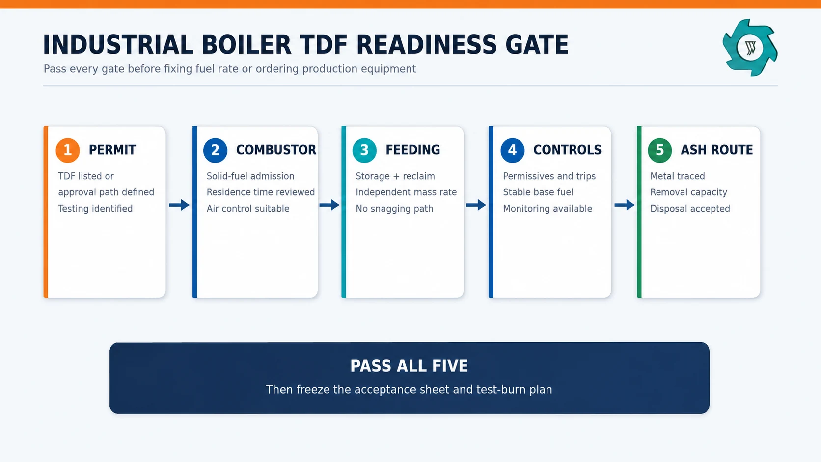
| Readiness question | Evidence to request | Reason to stop or redesign |
|---|---|---|
| Is TDF an allowed fuel? | Current permit conditions, proposed modification path, applicable testing and recordkeeping | The fuel is absent from the permitted envelope or approval depends on uncompleted testing |
| Can the furnace accept solids at the intended point? | Boiler drawings, admission location, residence-time and temperature review | Fuel can bypass the intended combustion zone or enter faster than it can burn out |
| Can the plant meter TDF independently? | Feeder range, turndown, calibration method and mass-flow verification | The plant can only infer TDF flow from belt speed or loader batches |
| Are controls and trips defined? | Cause-and-effect chart, permissives, alarms and loss-of-feed response | TDF can continue while base fuel, combustion air or downstream equipment is unavailable |
| Can ash and metal be handled? | Bottom/fly ash route, magnetic or screening provisions, disposal acceptance | Wire or changed ash chemistry creates blockage, equipment damage or disposal conflict |
Write a Boiler-Specific TDF Acceptance Sheet
ASTM D6700 is useful because it frames TDF around combustion, handling, environmental and residue considerations rather than one universal grade.3 In procurement, each acceptance field needs four elements: a limit, a test method, a sampling frequency and the party responsible for the decision.
The YUXI Tire TDF Plant publishes 50–80 mm as a standard target and an approximate 50–150 mm adjustable range. Those values describe production capability, not boiler acceptance. The receiver’s maximum piece, oversize tolerance and measuring convention take priority.
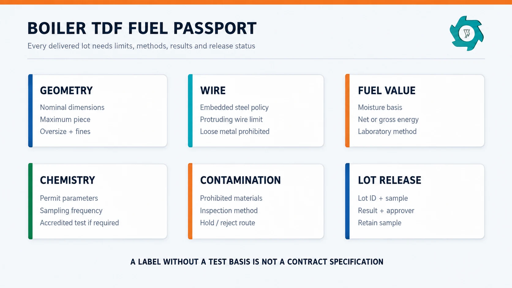
| Specification field | Put this in writing | Why the boiler cares |
|---|---|---|
| Particle envelope | Nominal dimensions, maximum piece, oversize mass fraction, fines definition and test screen or measurement method | Controls bridging, feeder bite, pneumatic or mechanical transfer, burnout and carryover |
| Steel condition | Embedded steel policy; maximum protruding wire; loose-metal prohibition; test and reporting basis | Long wire can snag; liberated metal can damage equipment; retained steel moves into ash |
| Moisture | As-received limit and test method | Changes net energy, flow behavior and the true heat-substitution calculation |
| Energy value | Gross or net calorific value, laboratory method, as-received or dry basis | Needed to convert mass flow into heat input and compare with base fuel |
| Chemistry | Locally required sulfur, chlorine, metals or other parameters, with accredited test basis where required | May affect emissions, corrosion, ash and permit compliance |
| Foreign material | Explicit prohibited list: rims, stones, free liquid, soil, wood, plastics or other non-tire material | Protects the fuel system and prevents uncontrolled input variability |
| Lot identity | Lot boundary, sample protocol, certificate fields, retain sample and rejection procedure | Makes a nonconforming delivery traceable and commercially resolvable |
For the detailed logic behind measurement fields, use the TDF quality specifications guide. For a boiler contract, add feeder-specific maximum dimensions and a clearly defined wire-snag criterion.
Steel-In Is Not the Same as Uncontrolled Wire
A boiler may accept some tire steel, yet still reject long protruding strands or loose bead wire. Embedded reinforcement tends to travel with the rubber chip. Exposed wire can hook across chutes, screws, rotary valves or transition points. Loose metal can segregate during transport and arrive as a concentrated slug.
EPA notes that retained metal ends in the ash and can create disposal issues.1 The receiver should therefore trace steel through the full route: truck unloading, reclaim, metering, combustion, bottom ash, fly ash and disposal or beneficial use. If the plant needs a lower-wire product, the TDF steel-wire requirements guide can support the upstream choice between bead treatment, further liberation and magnetic separation.
Design the Receiving and Feeding Route Backward from the Furnace
A robust system usually separates storage, reclaim, metering and final admission. The day bin buffers delivery variation. A live-bottom, agitator or other suitable reclaim arrangement prevents stable arches from being mistaken for an empty bin. A weigh feeder or loss-in-weight system establishes mass flow. The final conveyor, screw, airlock or chute then presents fuel to the approved combustion point.
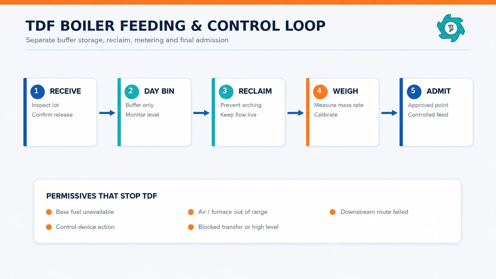
Use mass flow, not volume alone
TDF bulk density changes with chip geometry, wire, fines and compaction. A screw revolution or belt speed can remain constant while the actual fuel mass changes. Calibrate the feeder with collected or reconciled mass over time, then verify it periodically. If a volumetric device is unavoidable, establish a defensible conversion range and treat bulk-density drift as an operating uncertainty.
Report both mass rate and heat share. A permit may use one basis, while combustion engineers need the other. EPA’s historical FAQ describes successful supplementary use in properly designed combustors with good combustion control and particulate controls, but this is evidence of conditional feasibility, not a universal operating target.4
Interlock the entire fuel path
The TDF feeder should stop on loss of required base fuel, insufficient combustion air, furnace or bed conditions outside the approved window, downstream conveyor failure, high bin level at a blocked transfer, combustion-control trip, or an emissions/control-device condition defined by the plant. Shutdown sequence matters: stop upstream input, clear or secure the remaining fuel as designed, and prevent a restart into a plugged route.
| Observed condition | Immediate control response | Engineering follow-up |
|---|---|---|
| Unstable feeder mass rate | Hold or reduce TDF; maintain approved base-fuel operation | Check bridging, calibration, variable bulk density and refill disturbance |
| Repeated wire snag | Stop the affected route safely | Locate the catch point; tighten exposed-wire limit or redesign transition |
| Unburned chip or carryover | Step back TDF rate under the test plan | Review particle maximum, admission point, residence time and combustion conditions |
| CO, opacity or another monitored value approaches action level | Follow the approved operating and permit response | Correlate fuel lot, rate, air distribution, load and control-device operation |
| Ash removal overload | Prevent accumulation from reaching an unsafe state | Measure metal and ash balance; revise fuel limit or removal capacity |
Commission with a Stepwise Test Burn
Establish stable base-fuel performance first. Confirm instrumentation and feeder calibration. Introduce the lowest approved TDF step, hold it long enough to observe both combustion and material transport, then increase only under the written plan.
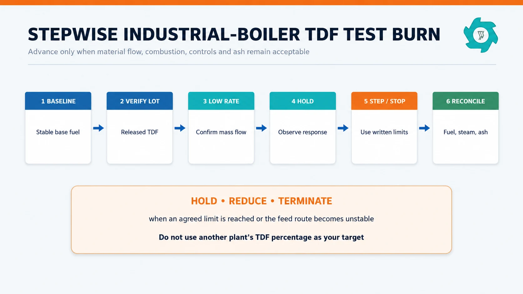
- Baseline: record boiler load, base-fuel rates, steam output, air distribution, temperatures, draft, monitored emissions indicators and ash operation.
- Fuel verification: release a traceable TDF lot and retain its sample and certificate.
- Low-rate admission: verify actual mass flow, route stability and correct interlock behavior.
- Hold and observe: allow transport and combustion effects to reach the relevant monitoring points.
- Step or stop: increase only if every agreed criterion is acceptable; otherwise hold, reduce or terminate.
- Reconcile: compare TDF mass and heat input with steam, base-fuel displacement, ash and operating observations.
A New York permit review report for one circulating fluidized-bed facility, for example, documented explicit weight-based TDF limits and stated that the feed rate could be modified following authorized operational test burns and performance stack tests.5
Practical Limits That Usually Set the Ceiling
The highest mechanically achievable feed rate is rarely the project limit. The sustainable ceiling is the lowest of several constraints:
- Permit limit: allowed fuel, rate basis, emissions conditions, monitoring and reporting.
- Feeder turndown: ability to meter low and high rates without surging or starvation.
- Combustion limit: stable burnout, temperatures, draft, air distribution and acceptable CO or other indicators.
- Control-device limit: particulate loading and operation within the approved range.
- Ash limit: bottom/fly ash removal, retained steel and disposal acceptance.
- Fuel-quality limit: chip maximum, exposed wire, moisture or chemistry variability.
- Storage and logistics limit: safe inventory, reliable reclaim and delivery continuity.
For stockpiles, conveyors, moisture and fire planning, see the TDF storage and handling guide. The industrial-boiler decision is how storage behavior affects continuous metering and trip recovery.
Calculate Performance on Accepted Energy, Not Delivered Tonnes
Delivered tonnes can hide rejects, moisture variation and off-spec lots. Boiler economics should separate the processor’s accepted output from the receiver’s usable energy. At minimum, report:
Track base-fuel displacement over comparable load periods, but do not claim that every unit of TDF heat displaces an equal unit of purchased fuel. Boiler efficiency, moisture, unburned material, auxiliary power and operating constraints can change. A short trial can demonstrate operability; it may not establish annual economics across seasonal load and fuel variation.
What the TDF Producer Should Prove
The upstream line should be tested against the boiler’s acceptance sheet. State capacity as accepted finished tonnes per hour after the process reaches stable operation. Record representative tire mix, screen opening, oversize return, rejects, steel-removal route, run time and downtime. Raw tire input is still useful, but it must not be presented as conforming output.
When output drifts, use the TDF plant troubleshooting guide to separate blade wear, screen/return behavior, bridging and feed variability.
RFQ Checklist Before Equipment Selection
| Boiler plant provides | TDF producer provides | Both parties agree |
|---|---|---|
| Boiler and combustion type; permitted fuel envelope; admission point; normal and minimum load; ash route | Tire categories and maximum size; contamination controls; proposed preparation stages; representative production data | Particle and wire limits; moisture/energy basis; prohibited material; lot and sample rules |
| Feeder arrangement, minimum/maximum mass rate, interlocks, receiving and storage constraints | Accepted-output rate; screen and return basis; steel-control method; dispatch form | Delivery rate; certificate fields; rejection/hold process; change control |
| Test-burn approvals, monitoring, action limits and reporting requirements | Trial lot quantity, retain sample and production traceability | Step sequence, hold time, pass/fail criteria, stop conditions and responsibility |
Configure the TDF Line Around the Boiler
Send the boiler’s written fuel specification, intended delivery form, representative tire mix and required accepted output. YUXI can match tire preparation, shredding, screening, oversize return and steel control to the receiver’s measurable limits.
FAQ: TDF for Industrial Boilers
Can any industrial boiler burn TDF?
No. The boiler, fuel-feed route, combustion controls, particulate controls, ash system and permit must all be suitable. A conventional gas- or oil-only boiler is not made TDF-ready by adding a conveyor.
What TDF chip size should an industrial boiler use?
There is no universal size. The written limit must match the feeder opening, transfer geometry, grate or combustion zone and residence time. Specify nominal dimensions, maximum piece and oversize tolerance together.
Does boiler TDF have to be wire-free?
Not always, but embedded steel, protruding wire and loose metal must be treated as separate acceptance questions. The receiving plant must evaluate feeding, ash handling and disposal before setting measurable limits.
How should TDF be introduced during a boiler trial?
Start only under an approved test plan at stable base-fuel operation. Increase TDF in defined steps, hold each step long enough to observe combustion and material flow, and stop or step back when a written limit or feed-system condition is reached.
What is the most useful TDF feed-rate metric?
Use a measured mass rate and also report TDF as a share of total heat input. A weight percentage alone can misstate thermal substitution because the fuels may have different moisture and heating values.
What should be confirmed before ordering a TDF production line?
Obtain the boiler operator’s written fuel specification, delivery form, sampling method, required accepted tonnage and test-burn plan. Then match shredding, screening, steel control and dispatch to those requirements.
Engineering References
- U.S. EPA, TDF guidance. Scrap tire fuel context.
- U.S. EPA, air implications. Tire-fuel technical review.
- ASTM International, D6700 standard. Scrap-tire-derived fuel guide.
- U.S. EPA, TDF FAQ. Frequently asked TDF questions.
- New York DEC, permit report. Industrial boiler example.